Special gear for optical fiber rotary connector

A technology of rotating connectors and gears, applied in the direction of belts/chains/gears, components with teeth, coupling of optical waveguides, etc., can solve the problems of large size and heavy weight of products, and reduce the number of parts and fixing parts, the effect of speeding up assembly efficiency

Inactive Publication Date: 2020-01-17
安徽澜轩光电科技有限责任公司
View PDF9 Cites 0 Cited by
  • Summary
  • Abstract
  • Description
  • Claims
  • Application Information

AI Technical Summary

Benefits of technology

This innovation allows for better integration between circular part components onto teeth with fewer parts that are easier or faster than traditional methods like welding them together. It also makes it possible to make products smaller without having many unnecessary features such as fixing certain things on their own.

Problems solved by technology

This patented describes how certain types of fibers can rotate smoothly during connection or communication with another type of lightweight device called a lens (optic). However, there are some issues related to this design: adding extra components makes the assembly heavier than usual due to added massiness caused by these devices themselves.

Method used


Image

  • Special gear for optical fiber rotary connector

Examples


Embodiment Construction

[0014] The present invention will be further described below in conjunction with embodiment.

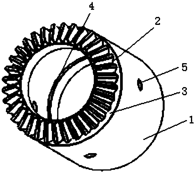
[0015] Such as figure 1 The shown special gear for optical fiber rotary connector includes a hollow cylinder 1, and a bevel tooth structure 2 is processed on one end surface of the cylinder 1 to form a bevel gear. An annular groove 3 is provided at the position of the tail of the bevel teeth in the circumferential direction of the cylinder body 1 . A card slot 4 is processed on the inner wall of the cylinder body 1, and the card slot is convenient for connecting with other parts. In the barrel 1, the inner diameter of the barrel at one end of the bevel gear is smaller than the inner diameter of the other parts of the barrel, and the inner wall of the barrel forms a stepped structure. A through hole 5 that runs through the cylinder is processed on the cylinder. The bevel gears are straight bevel gears or bevel bevel gears.

[0016] The basic principles, main features and advantage...


PUM


Abstract

The invention provides a special gear for an optical fiber rotary connector. The special gear comprises a hollow cylinder body, wherein a conical tooth structure is machined on one end face of the cylinder body to form a bevel gear, an annular groove is arranged in the periphery of the cylinder body in the circumferential direction at the tail position of the conical tooth, a clamping groove is machined in the inner wall of the cylinder bod, the inner diameter of the cylinder body at one end of the conical tooth in the cylinder body is smaller than the inner diameter of the other part of the cylinder body, and a step structure is formed in the inner wall of the cylinder body; a through hole which penetrates through the cylinder body is machined in the cylinder body, and the bevel gear is astraight tooth bevel gear or a bevel gear bevel gear. The special gear has the beneficial effects that cylindrical parts are integrated into the gear, the machining is more convenient and faster, thenumber of parts is reduced, the assembling efficiency of the product is accelerated, fixing parts of the parts are reduced, and the overall size of products is reduced.

Description


Claims


Application Information

Patent Timeline
Owner 安徽澜轩光电科技有限责任公司
Why Eureka
Try Eureka