Acoustic and electronic equipment

A technology for acoustic devices and electronic equipment, applied in the field of acoustic devices and electronic equipment, can solve the problems of inability to improve the low frequency band, poor effect of low frequency band sensitivity improvement, negative sensitivity of the acoustic system, etc., to increase the equivalent sound smoothness and improve Low-frequency sensitivity, the effect of lowering the resonance frequency

Active Publication Date: 2022-07-12
GEER TECH CO LTD
View PDF14 Cites 0 Cited by
  • Summary
  • Abstract
  • Description
  • Claims
  • Application Information

AI Technical Summary

Problems solved by technology

[0003] However, there are problems in the above two methods. When the size and volume of the cavity are limited, the first method is not effective in improving the low-frequency sensitivity by filling sound-absorbing materials; the second method uses passive radiators. Near the resonant frequency point fp, the passive radiator radiates strongly, and the sound unit almost stops, so the local sensitivity enhancement of the acoustic system can be realized in the frequency band near fp through the high-sensitivity design of the passive radiator; but in the frequency band below fp, the passive radiator The sound waves are in opposite phase to the sounding unit, the sound waves cancel each other out, passive radiators have a negative effect on the sensitivity of the acoustic system
All in all, passive radiators can only improve the sensitivity of the frequency band near the resonance point, but cannot improve the sensitivity of all low frequency bands, so it is necessary to make further improvements to the defects of the existing technology

Method used


Image

  • Acoustic and electronic equipment
  • Acoustic and electronic equipment
  • Acoustic and electronic equipment

Examples


Embodiment Construction

[0034] Various exemplary embodiments of the present invention will now be described in detail with reference to the accompanying drawings. It should be noted that the relative arrangement of components and steps, the numerical expressions and numerical values ​​set forth in these embodiments do not limit the scope of the invention unless specifically stated otherwise.

[0035] The following description of at least one exemplary embodiment is merely illustrative in nature and is in no way intended to limit the invention, its application, or uses in any way.

[0036] Techniques, methods, and apparatus known to those of ordinary skill in the relevant art may not be discussed in detail, but where appropriate, such techniques, methods, and apparatus should be considered part of the specification.

[0037] In all examples shown and discussed herein, any specific values ​​should be construed as illustrative only and not limiting. Accordingly, other instances of the exemplary embodim...


PUM


Abstract

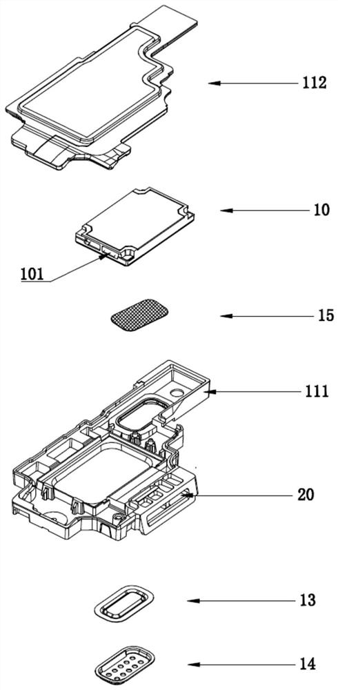
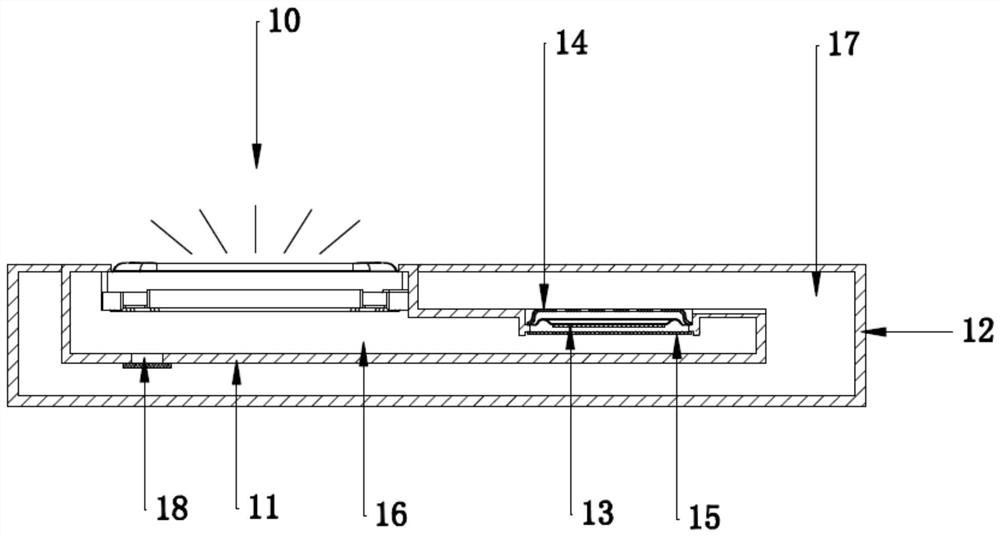
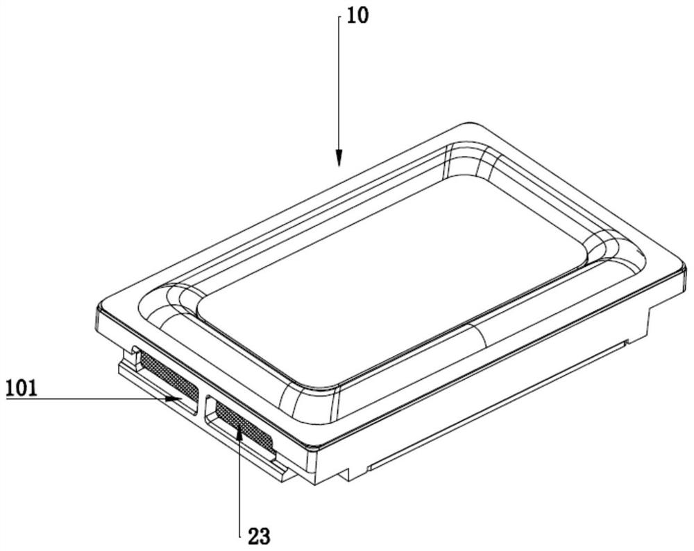
The invention discloses an acoustic device, comprising a sounding unit and a first casing, the sounding unit includes a vibrating diaphragm, the first casing and the vibrating diaphragm are enclosed to form a first airtight cavity, and an installation hole is opened on the first casing, The installation hole is provided with a flexible deformation part covering the installation hole, the outer side of the first closed cavity is provided with a second closed cavity, the flexible deformation part is located between the first closed cavity and the second closed cavity, and the installation hole is provided with a covering installation hole The first air-permeable spacer is located in the first airtight cavity, the first airtight space is further provided with a second air-permeable spacer, and the first airtight cavity is filled with sound-absorbing material. The invention also discloses an electronic device, which includes a casing and the above acoustic device. The acoustic device of the present invention has excellent acoustic performance.

Description

technical field [0001] The present invention relates to the technical field of acoustics, and more particularly, to an acoustic device and an electronic device equipped with the acoustic device. Background technique [0002] Generally speaking, an acoustic system with a traditional structure includes a closed box and a sound-generating unit arranged on the closed box. A cavity is formed between the closed box and the sound-generating unit. Due to the volume limitation of the cavity in the acoustic system, the acoustic system Especially small acoustic systems are difficult to achieve satisfactorily reproduce bass. Conventionally, in order to achieve a satisfactory bass reproduction in an acoustic system, two means are usually used, one is to place a sound-absorbing material (such as activated carbon, zeolite, etc.) in the cabinet of the acoustic system for adsorption or desorption of the cabinet. The gas in the body has the effect of increasing the volume and reducing the lo...

Claims


Application Information

Patent Timeline
Patent Type & Authority Patents(China)
IPC IPC(8): H04R9/06H04R9/02
CPCH04R9/06H04R9/02H04R2400/11
Inventor 郑泽东徐同雁张洪鹏
Owner GEER TECH CO LTD
Why Eureka
Try Eureka