
Shifting fork type mechanism for stopping transplanting in backward movement and rice transplanter

A technology of fork type and fork assembly, which is applied to transplanting machinery, controlled components, mechanical equipment, etc., can solve the problems of poor reliability, one-way clutch heating, high failure rate, simple and reliable structure, and increased self-locking. The effect of strong force and environmental adaptability

Pending Publication Date: 2020-01-21
LOVOL HEAVY IND
View PDF0 Cites 1 Cited by
  • Summary
  • Abstract
  • Description
  • Claims
  • Application Information

AI Technical Summary

Problems solved by technology

[0002] The rice transplanter is a kind of agricultural machinery for implanting rice seedlings into the rice field. The rice transplanter includes a traveling part and a rice transplanting part. The rice transplanting part is connected to the rear end of the traveling part. The traveling part drives the transplanting part to move. During the working process, when the traveling part drives the rice transplanting part forward, the rice transplanting part performs rice transplanting, and when the traveling part drives the rice transplanting part backwards, the rice transplanting part stops working and does not perform rice transplanting. In order to achieve this purpose, the existing rice transplanter uses a one-way clutch bearing Connect the traveling power output shaft and the rice transplanting power input shaft, so that when the traveling part moves forward, the power output by the traveling power output shaft can be transmitted to the rice transplanting power input shaft through the one-way clutch bearing to provide power for the rice transplanting part to perform rice transplanting. When the traveling part is reversed, The one-way clutch bearing is idling, and the power of the traveling power output shaft cannot be transmitted to the rice planting power input shaft through the one-way clutch bearing, and there is no power input to the rice planting part
[0003] The method of using the one-way clutch bearing to connect the driving power output shaft and the rice transplanting power input shaft mainly has the following problems: First, after the gearbox is used for a long time, the internal oil becomes dirty and there are impurities in the oil, which will affect the one-way clutch bearing Rotation, the one-way clutch bearing will produce poor rotation such as insufficient locking force of the ball or slipping; second, when the engine rotates at high speed, the forward and reverse switching is frequent, and frequent switching will cause the one-way clutch to heat up and cause sintering and other failures; It is to cut off the power of the rice transplanting part and ensure that the rice transplanting part does not transplant rice seedlings when the whole machine is reversed. The one-way clutch bearings are all assembled inside the gearbox. When the one-way clutch bearings with limited bearing capacity fail, the workload of replacement and maintenance will be large.
[0004] The existing one-way clutch bearing is used to connect the traveling power output shaft and the rice transplanting power input shaft to ensure that the rice transplanter is reversed without planting rice. inconvenient

Method used


Image

  • Shifting fork type mechanism for stopping transplanting in backward movement and rice transplanter
  • Shifting fork type mechanism for stopping transplanting in backward movement and rice transplanter
  • Shifting fork type mechanism for stopping transplanting in backward movement and rice transplanter

Examples


Embodiment Construction

[0036] In order to make the object, technical solution and advantages of the present invention clearer, the present invention will be further described in detail below in conjunction with the accompanying drawings.

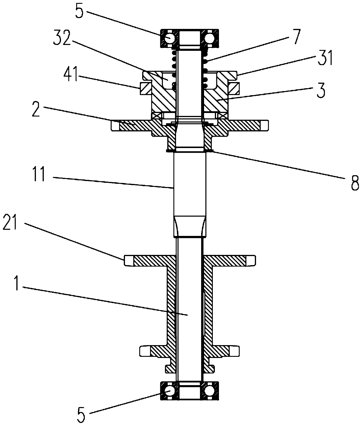
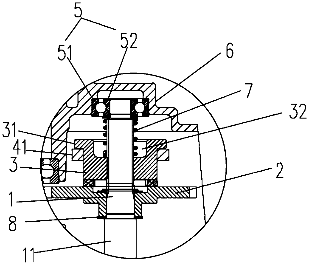
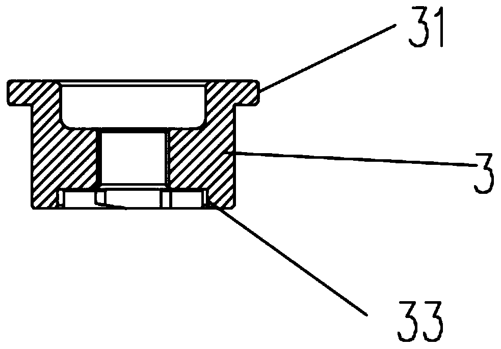
[0037] Such as Figure 1-Figure 6 As shown, the embodiment of the fork-type reverse non-planting mechanism disclosed by the present invention includes a fork assembly, a rice-planting power input shaft 1, a rice-planting input gear 2, a clutch 3 and a spring 7, and the two ends of the rice-planting power input shaft 1 respectively pass through The bearing 5 is rotationally connected with the inner walls on both sides of the gearbox 6. The input gear 2, the clutch 3 and the spring 7 are all socketed on the power input shaft 1 for rice transplanting. The input gear 2 for rice transplanting is an idler gear. The power input shaft 1 is connected by transmission, the surface of the rice transplanting power input shaft 1 has a limiting portion 11, the rice transplanting...


PUM


Abstract

The invention discloses a shifting fork type mechanism for stopping transplanting in backward movement. The shifting fork type mechanism comprises a shifting fork component, a rice transplanting powerinput shaft, a rice transplanting input gear, a clutch and a spring. The shifting fork component is connected with a gear change hand lever, the rice transplanting power input shaft is connected witha rice transplanting mechanism, the rice transplanting input gear is connected with an advancing portion gear, and the rice transplanting input gear, the clutch and the spring sequentially sleeve therice transplanting power input shaft. The rice transplanting input gear is in clearance sleeve connection with the rice transplanting power input shaft, and the clutch and the rice transplanting power input shaft are in transmission connection and slide fit. The rice transplanting power input shaft is provided with a limiting portion, the rice transplanting input gear is positioned between the limiting portion and the clutch, ends of the rice transplanting input gear and the clutch are provided with matched meshed teeth, two ends of the spring are abutted against the clutch and a gearbox respectively, the clutch is provided with a shifting portion, and the shifting fork component is positioned between the shifting portion and the rice transplanting input gear. The invention further discloses a rice transplanter with the shifting fork type mechanism for stopping transplanting in backward movement. The rice transplanter and the shifting fork type mechanism for stopping transplanting inbackward movement have advantages of low fault rate and high reliability.

Description

technical field [0001] The invention relates to the field of agricultural machinery, in particular to a fork-type reversing non-transplanting mechanism and a rice transplanter. Background technique [0002] The rice transplanter is a kind of agricultural machinery for implanting rice seedlings into the rice field. The rice transplanter includes a traveling part and a rice transplanting part. The rice transplanting part is connected to the rear end of the traveling part. The traveling part drives the transplanting part to move. During the working process, when the traveling part drives the rice transplanting part forward, the rice transplanting part performs rice transplanting, and when the traveling part drives the rice transplanting part backwards, the rice transplanting part stops working and does not perform rice transplanting. In order to achieve this purpose, the existing rice transplanter uses a one-way clutch bearing Connect the traveling power output shaft and the ri...

Claims


Application Information

Patent Timeline
IPC IPC(8): A01C11/00F16H63/32
CPCA01C11/003A01C11/006F16H63/32F16H2063/321F16H2063/325
Inventor 朱克成刘文忠李玉彪于克港刘然
Owner LOVOL HEAVY IND
Learn More