Granary pest snapshot system based on machine vision

A machine vision and granary technology, applied in the field of granary pest capture system based on machine vision, can solve the problems of lack of comparability, unstable results, poor effect, etc., and achieve the effect of improving efficiency, high accuracy, and saving labor

Pending Publication Date: 2020-01-21
JINAN JINZHONG ELECTRONICS SCALE
0 Cites 0 Cited by

AI-Extracted Technical Summary

Problems solved by technology

The trapping method uses the biological characteristics of pests (phototaxis, pheromones, attractants) to trap pests. This method is less effective for pests that do not like sports, and t...

Method used

The present invention can utilize air pump 5, the pest that is embedded in the trap 1 in the grain pile is extracted out, by the pipeline of channel selector 2 pest is transported on the capture platform 13 outside the storehouse, then control software issues capture Order, the machine vision camera 8 that is arranged on the capture platform 13 tops captures the pests collected, and after the capture is completed, the pest photos are uploaded to the computer 6 software platform, and the pests are identified using big data to determine the type and quantity. After the capture is completed, the flipping device 16 connected to the capture platform turns the capture platform 13 18...

Abstract

The invention discloses a granary pest snapshot system based on machine vision. The granary pest snapshot system comprises a trap, a pest detecting device, a channel selector, a gas detector, an air pump, a computer and a control cabinet, wherein the trap is arranged inside a granary; the gas detector and the air pump are arranged in the control cabinet, and the control cabinet is arranged outsidethe granary; the trap is communicated with the pest detecting device through the channel selector; the pest detecting device is communicated with the gas detector through a gas pipeline; the gas detector is communicated with the air pump through a gas pipeline; the gas detector and the pest detecting device are connected to the computer. The granary pest snapshot system has the advantages that the sampling method and the trapping method of manual pest detection are combined, the air pump pumping manner is adopted, manpower can be saved, efficiency can be increased, high accuracy can be achieved, and pictures can be stored and recorded.

Application Domain

Character and pattern recognitionInsect catchers and killers

Technology Topic

Gas pipelineAgricultural engineering +8

Image

  • Granary pest snapshot system based on machine vision
  • Granary pest snapshot system based on machine vision

Examples

  • Experimental program(1)

Example Embodiment

[0035] The technical solutions in the embodiments of the present invention will be clearly and completely described below with reference to the accompanying drawings. Obviously, the described embodiments are only a part of the embodiments of the present invention, rather than all the embodiments. Based on the embodiments of the present invention, all other embodiments obtained by those of ordinary skill in the art without creative work shall fall within the protection scope of the present invention.
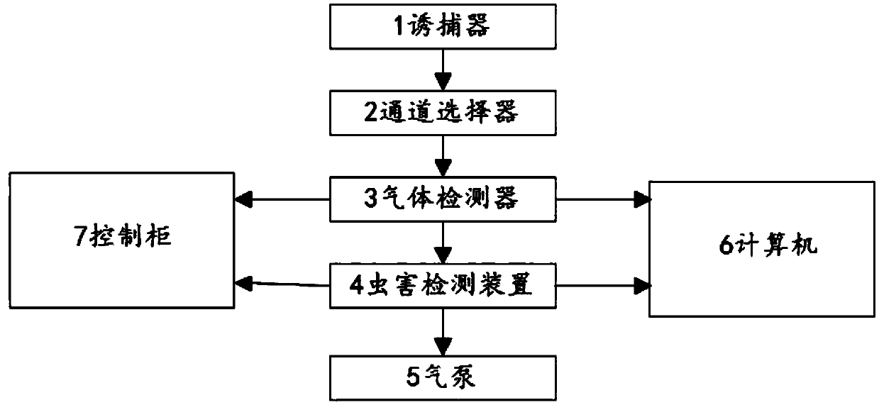
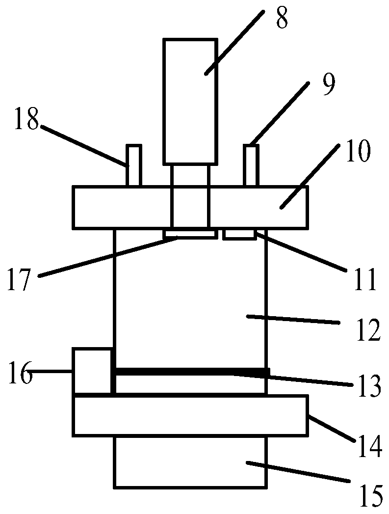
[0036] Such as Figure 1-2 As shown, a granary pest capture system based on machine vision includes a trap 1, a channel selector 2, a gas detector 3, a pest detection device 4, an air pump 5, a computer 6, a control cabinet 7; the trap 1 is set up Inside the granary, it is used to catch pests in the grain pile in the silo. There can be multiple traps 1 according to specific conditions; the trap 1 and the pest detection device 4 are selected through the channel The channel selector 2 includes a disc and a sub-port; one end of the trap 1 is connected to the sub-port through a gas pipeline, and the other end of the trap 1 is connected to the sub-port through a gas pipeline. The air inlet 9 is in communication, and the channel selector 2 can take turns to extract pests from the trap 1 in different areas of the granary.
[0037] The pest detection device 4 communicates with the gas detector 3 through a gas pipeline; the pest detection device 4 includes a machine vision camera 8, an air inlet 9, an upper cover 10, a fill light 11, and a device main body 12. The capture platform 13, the connecting plate 14, the collection box 15, the plate turning device 16, the glass cover 17, the air outlet 18; the machine vision camera 8, the air inlet 9 and the air outlet 18 are arranged on the On the upper part of the cover plate 10, the fill light 11 and the glass cover plate 17 are arranged on the lower part of the upper cover plate 10; the upper cover plate 10 is arranged on the device main body 12, and the connecting plate 14 is arranged on Below the device main body 12; the capture platform 13 is arranged inside the device main body 12; the plate turning device 16 is arranged on the upper part of the connecting plate 14; the collection box 15 is arranged on the lower part of the connecting plate 14, The collection box 15 is used to collect pests. One end of the gas detector 3 communicates with the gas outlet 18 through a gas pipeline, and the other end of the gas detector 3 communicates with the gas pump 5 through a gas pipeline. The gas detector 3 is in communication with the gas pump 5 through a gas pipeline. The gas pump 5 can be used as a power source for extracting gas and pests in the granary, and the gas detector 3 is used to detect The concentration of oxygen, carbon dioxide, and phosphine gas; the gas detector 3 and the pest detection device 4 are respectively connected to the computer 6, and the computer 6 can analyze and display the captured photos and gas data, so The machine vision camera 8 is connected to the computer 6. The gas detector 3 and the gas pump 5 are arranged in the control cabinet 7, and the control cabinet 7 is arranged outside the granary. The above-mentioned components are all connected by gas pipelines and used to transport the gas and pests in the extracted granary.
[0038] The present invention can use the air pump 5 to extract the pests collected in the trap 1 buried in the grain pile, and transport the pests to the capture platform 13 outside the warehouse through the pipeline of the channel selector 2, and then control the software to issue the capture command and set The machine vision camera 8 on the upper part of the capture platform 13 captures the collected pests. After the capture is completed, the pest photos are uploaded to the computer 6 software platform, and the big data is used to identify the pests and determine the type and quantity. After the capture is completed, the flipping device 16 connected to the capture platform turns the capture platform 13 by 180°, and pours the collected pests into the collection box 15 at the bottom of the collection bottle, and then resets the device to prepare for the next capture. At the same time, the The invention can detect the concentration of oxygen, carbon dioxide, phosphine and other gases in the granary through the gas detector 3, and analyze and display the gas data in the granary through the computer 6; the present invention combines the sampling method for manual detection of pests and The combination of trapping method and air pump extraction can realize the functions of automatic sampling of pests and automatic identification of pests, and can save labor and improve efficiency. The software system can analyze the captured photos of pests with high accuracy and Store and record photos.
[0039] The working process of the present invention is that when the system receives the capture command, the air pump 5 starts to work to extract the pests in the trap 1, and the pests enter the device through the channel selector 2 in the air pipeline, and enter through the air inlet 9. Falling on the capture platform 13, the machine vision camera 8 takes pictures of the pests on the capture platform 13, and transmits the photos to the computer 6. The computer 6 can use big data to identify the pests, determine the type and quantity, and flip the board after the shooting is completed. The device 16 turns the capture platform 13 by 180°, the pests fall into the collection box 15, and the flap device 16 automatically resets, waiting for the capture of the next channel. At the same time, the gas in the granary enters the gas detector 3 through the gas outlet 18 The gas detector 3 detects the concentration of oxygen, carbon dioxide, phosphine and other gases in the granary, and the computer 6 analyzes and displays the gas data in the granary.
[0040] The above descriptions are only preferred embodiments of the present invention and are not intended to limit the present invention. Any modification, equivalent replacement, improvement, etc. made within the spirit and principle of the present invention shall be included in the protection of the present invention. Within range.

PUM

no PUM

Description & Claims & Application Information

We can also present the details of the Description, Claims and Application information to help users get a comprehensive understanding of the technical details of the patent, such as background art, summary of invention, brief description of drawings, description of embodiments, and other original content. On the other hand, users can also determine the specific scope of protection of the technology through the list of claims; as well as understand the changes in the life cycle of the technology with the presentation of the patent timeline. Login to view more.

Similar technology patents

Swinging spinning and winding noodle extension machine

Owner:巴彦淖尔市冠生园食品有限责任公司

Grabbing manipulator for carrier roller

InactiveCN105414961Alabor savingImprove efficiency
Owner:SHANXI GUDE BAOFENG HEAVY IND MACHINERY

Full-automatic areca catechu equal slicer

Owner:湖南和畅实业集团有限公司

Classification and recommendation of technical efficacy words

Why Eureka
Try Eureka