Foot-controlled gas flow rate device for controlling gas supply device and gas injection stripping system

A technology of gas flow rate and air supply device, which is applied in the parts of surgical instruments, medical science, heating surgical instruments, etc., can solve the problems of inability to effectively realize jet separation, inability to accurately realize surgical treatment, etc., and achieve convenient surgical cutting operations. , Improve the effect of surgical safety factor

Pending Publication Date: 2020-01-21
BEIJING TONGREN HOSPITAL AFFILIATED TO CAPITAL MEDICAL UNIV
View PDF10 Cites 0 Cited by
  • Summary
  • Abstract
  • Description
  • Claims
  • Application Information

AI Technical Summary

Problems solved by technology

[0005] The purpose of the present invention is to provide a foot-controlled gas flow rate device and an air-jet peeling system for controlling the air supply device in the air-jet peeling system; through the design of the foot-controlled gas flow rate device and the air-jet peeling control system to sol...

Method used


Image

  • Foot-controlled gas flow rate device for controlling gas supply device and gas injection stripping system
  • Foot-controlled gas flow rate device for controlling gas supply device and gas injection stripping system
  • Foot-controlled gas flow rate device for controlling gas supply device and gas injection stripping system

Examples


Embodiment 2

[0078] Such as Picture 10 As shown, the difference between this embodiment and the first embodiment is only the opening position of the outlet port 3. The technical content disclosed in the first embodiment is not described repeatedly, and the content disclosed in the first embodiment also belongs to the content disclosed in this embodiment.

[0079] Such as Figure 7 As shown, this embodiment provides an air jet stripping electric cutting head, which includes a metal tube body 1 with a gas flow channel 4 inside. One end of the metal tube body 1 is closed, and the other end is provided with an air inlet port communicating with the gas flow channel 4 2. The outer wall of the metal tube 1 or / and the metal tube 1 close to the metal tube 1 is provided with an outlet port 3 communicating with the gas flow channel 4; the inner diameter of the gas flow channel 4 is determined by the inlet The air port 2 gradually decreases toward the air outlet port 3 or decreases in steps; the specific...

Embodiment 3

[0084] Such as Picture 12 As shown, the metal pipe body 1 in the present invention is an improvement based on the first embodiment. The technical content disclosed in the first embodiment will not be described repeatedly, and the content disclosed in the first embodiment also belongs to the content disclosed in this embodiment.

[0085] The longitudinal section of the connecting section 101 in this embodiment is square.

[0086] In the present invention, the longitudinal section of the connecting section 101 is designed to be square to ensure the air intake of the metal pipe body 1 and the effective separation of the organs. At the same time, the longitudinal section of the connecting section 101 is a rectangular design, which is convenient for processing. The cross-section can be rectangular or square.

Embodiment 4

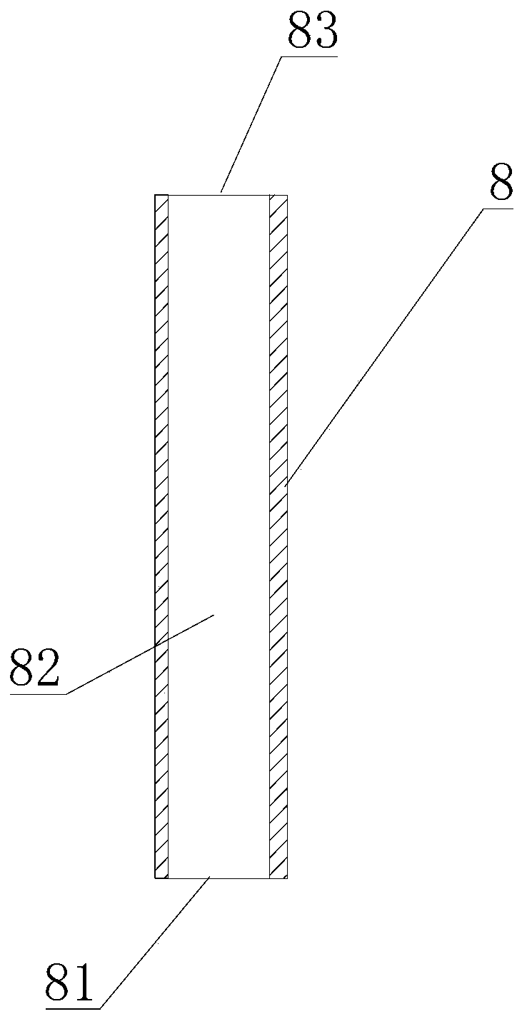
[0088] The difference between this embodiment and the first embodiment is only the location of the gas inlet 81. The technical content disclosed in the first embodiment will not be described repeatedly, and the content disclosed in the first embodiment also belongs to the content disclosed in this embodiment.

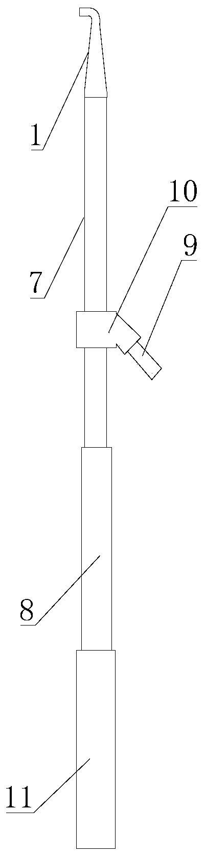
[0089] Such as Figure 13 , Figure 14 As shown, the gas inlet 81 and the conductive column 9 are separately provided on both sides of the metal gas pipe 7.

[0090] In the present invention, the gas inlet 81 and the conductive post 9 are separately arranged on both sides of the metal gas pipe 7, which facilitates the operator to observe the connection, and prevents the trachea or wire from falling off the gas inlet 81 and the conductive post 9 and affects the operation process.


PUM

PropertyMeasurementUnit
Inner diameteraaaaaaaaaa
Heightaaaaaaaaaa

Abstract

The present invention relates to a foot-controlled gas flow rate device for controlling a gas supply device in a gas injection stripping system and the gas injection stripping system. The foot-controlled gas flow rate device for controlling the gas supply device in the gas injection stripping system comprises an gas injection stripping electric cutting head, a metal air delivery pipe and a handlewhich are in successive connection and communication, also comprises a pedal pneumatic control device, and also comprises a controller and a gas flow rate data converter; one end of the handle communicates with a gas supply device through a gas pipe; the gas pipe communicates with a pneumatic control valve and a gas flow rate sensor; the pedal pneumatic control device comprises a fixed seat, a pedal is arranged above the fixed seat and fixedly connected with the fixed seat through an elastic connecting piece, a positioning chute is arranged in the fixed seat, a sliding rod is connected in thepositioning chute in a sliding manner and extends out of the positioning chute to be fixedly connected with the pedal, and a distance sensor is arranged at a bottom part of the sliding rod arranged inthe positioning chute; and the gas flow rate data converter is electrically connected with the controller and the pneumatic control valve is electrically connected with the controller. The foot-controlled gas flow rate device accurately realizes separation and treatment of organs in deep abdominal cavity.

Description

Technical field [0001] The present invention relates to the technical field of laparoscopic surgical instruments, in particular to a foot-controlled gas flow rate device and a jet stripping system for controlling an air supply device in a jet stripping system. Background technique [0002] Laparoscopic surgery is an operation performed using a laparoscope and related instruments. In order to have enough space for laparoscopic surgery, it is necessary to continuously infuse the abdominal cavity with carbon dioxide gas to establish an artificial pneumoperitoneum, which is a necessary condition for laparoscopic surgery. [0003] However, the existing equipment can only infuse gas into the abdominal cavity. In laparoscopic surgery, when dissecting the side or back of deep abdominal organs, tissue organs, or inflamed organs and surrounding tissues When there are close adhesions and need to be separated, or when the dissected organ is surrounded by important blood vessels and nerves, th...

Claims


Application Information

Patent Timeline
IPC IPC(8): A61B18/04
CPCA61B18/04A61B2018/048A61B2018/00607A61B2018/00315A61B2018/00863A61B2018/00744A61B2018/00982
Inventor 严立
Owner BEIJING TONGREN HOSPITAL AFFILIATED TO CAPITAL MEDICAL UNIV
Why Eureka
Try Eureka