Mounting device for wind power blade flasher

A wind power blade and installation device technology is applied in the field of wind power blade air-termination installation devices, which can solve the problems of inaccurate positioning, incomplete fastening of air-termination devices, and easy deviation of manually punched installation holes, so as to reduce operating strength and Difficulty, wide range of use, effect of installation and tightening

Active Publication Date: 2020-01-21
LUOYANG SUNRUI WIND TURBINE BLADE
14 Cites 9 Cited by

AI-Extracted Technical Summary

Problems solved by technology

[0004] In view of this, the object of the present invention is to provide a wind power blade air-termination installation device, which aims to solve the problems in...

Abstract

The invention discloses a mounting device for a wind power blade flasher. The mounting device comprises a pair of guide rails fixed on an upper bottom plate and sliding blocks which can slide up and down along the guide rails, a telescopic rod with a graduated scale fixed on the outer side surface is arranged on the two sliding blocks in parallel, a supporting plate is rotationally connected between the free ends of the two telescopic rods, and a plurality of suction cups are connected to the supporting plate; a first through hole for mounting a drill die is formed in the middle of the supporting plate, two mutually parallel guide rods are vertically arranged on the two sides of the first through hole, a sliding plate is arranged on the guide rods in a penetrating manner, the supporting plate is connected with the sliding plate through springs, a second through hole used for installing an electric drill is arranged in the middle of the sliding plate, a gear is rotationally connected with on one side, parallel to the telescopic rod, of the sliding plate, and the gear is meshed with a rack vertically fixed on the supporting plate; and the electric drill, the drill die and the auxiliary component cooperate to realize the installation of a flasher. According to the mounting device, the vertical degree of punching can be ensured, the punching process does not shake, the flasher is tightly installed, the operation difficulty of an operator is reduced, and the installation efficiency is improved.

Application Domain

Positioning apparatusPortable drilling machines +3

Technology Topic

Slide plateWind power +4

Image

  • Mounting device for wind power blade flasher
  • Mounting device for wind power blade flasher
  • Mounting device for wind power blade flasher

Examples

  • Experimental program(1)

Example Embodiment

[0030] It should be noted that the terms "comprising" and "having" and any variations thereof in the present invention are intended to cover non-exclusive inclusion, for example, a process, method, system, product or device that includes a series of steps or units does not necessarily Restricted to those steps or elements explicitly listed, but may include other steps or elements not explicitly listed or inherent to the process, method, product or apparatus.
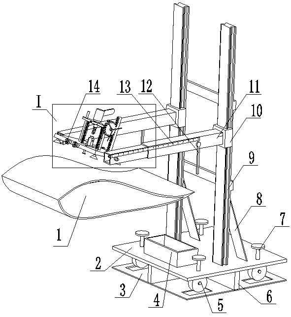
[0031] The core of the present invention is to provide a wind power blade air-termination installation device, which can effectively accurately locate the position where the wind power blade needs to be installed with the air-termination device, ensure the accuracy and verticality of the hole during the drilling process, and enable Lightning receptors are installed securely.
[0032] Please refer to figure 1 , figure 1 Schematic diagram of the structure provided by the present invention.
[0033] A wind power blade air-termination installation device provided by the present invention mainly includes in structure: an upper base plate 2, a lower base plate 3, a storage box 4, wheels 5, a vertical connecting plate 6, a screw rod 7, and a reinforcing rod 8, guide rail 9, slider 10, telescopic rod 11, gear rod 12, scale 13, support plate 14, locking wheel 15, drilling template 16, vertical detection rod 17, suction cup 18, screw sleeve 19, rotating shaft 20, Rotating rod 21, rack 22, gear 23, electric drill 24, locking bolt 25, spring 26, guide rod 27, slide plate 28, drill bit 29, drill sleeve 30, rotating cylinder 31.
[0034] A pair of guide rails 9 are vertically fixed on the upper surface of the upper bottom plate 2, and each guide rail 9 is provided with a slider 10 that cooperates with the guide rail 9 and can slide up and down along the guide rail 9. To adjust the height, the slider 10 is provided with a locking bolt, which can be locked after being adjusted to the target position. The two slide blocks 10 are parallelly provided with telescopic rods 11 perpendicular to the guide rails 10. The telescopic rods 11 are provided with fixing bolts capable of fixing the telescopic rods 11 that can be stretched to the target position. A scale is fixed on the outer surface of the telescopic rods 11. Ruler 13, the zero position of scale 13 is positioned at one end of telescopic rod 11 near guide rail 9, and telescopic rod 11 is provided with gear bar 12, and gear bar 12 is installed in the zero position of scale 13, makes gear bar 12 and wind power blade in use The rear edge of 1 is aligned, and the telescopic rod 11 can be adjusted according to the horizontal distance of the lightning receptor 32 from the rear edge side of the wind power blade 1, and the telescopic rod 11 is fixed with a fixing bolt after horizontal positioning.
[0035]The free ends of the two telescopic rods 11 are rotatably connected with a support plate 14, and both sides of the support plate 14 parallel to the telescopic rods are provided with a rotating shaft 20, and the rotating shaft 20 passes through the free ends of the corresponding side telescopic rods 11 and One end extending to the outside of the telescopic rod 11 is threadedly connected with a screw sleeve 19 , and the rotating shaft 20 drives the support plate 14 to rotate to a target angle to lock the rotating shaft 20 through the screw sleeve 19 .
[0036] like Figure 7 As shown, the middle part of the support plate 14 is provided with a through hole I 141, and the support plate 14 is vertically provided with two parallel guide rods 27 correspondingly distributed on both sides of the through hole I141, and each guide rod 27 is provided with a measuring scale, so The sliding plate 28 is provided with a guide groove compatible with the guide rod 27, the sliding plate 28 can move up and down along the guide rod 27, and a spring 26 is connected between the support plate 14 and the sliding plate 28, such as Image 6 As shown, the middle part of the sliding plate 28 is provided with a through hole II 281 corresponding to the through hole I for installing the electric drill 24, and the side wall of the sliding plate 28 is provided with a lock for locking the electric drill 24 that is threaded with the sliding plate 28. Tighten bolt 25, slide plate 28 is connected with gear 23 parallel to the side wall of telescoping rod 11, and described gear 23 is engaged with the tooth bar 22 that is vertically fixed on support plate 14, and gear 23 is arranged away from slide plate 28 one side. There is a rotating rod 21, and by rotating the rotating rod 21, the rack and pinion are engaged to realize the smooth movement of the sliding plate 28 up and down. As an embodiment of the present invention, the shape of the sliding plate 28 may include support plates at both ends and a ring fixed to each support plate in the middle (such as Image 6 shown). As another embodiment of the present invention, the shape of the sliding plate 28 may also be a rectangular plate with a through hole II 281 in the middle.
[0037] The drill template 16 used in conjunction with the auxiliary assembly is installed in the through hole I 141, and the drill template 16 includes a disc at the bottom and a prism fixed on the upper surface of the disc. The drill template 16 middle part is provided with a through hole III 161, and the electric drill 24. The drilling jig 16 cooperates with the punching assembly/air-termination installation assembly to realize the drilling/air-termination installation of the wind power blade 1.
[0038] It should be noted that the auxiliary components include a punching component and an air receptor installation component.
[0039] For details, please refer to Figure 2~Figure 3 , the drilling assembly includes a drill bit 29 detachably connected with the electric drill 24 and a drill sleeve 30 matched with the drill bit 29, the drill sleeve 30 placed in the through hole III 161 is detachably connected with the template 16, the support plate 14 Both side walls perpendicular to the telescopic rod 27 are provided with locking wheels 15 screwed to the support plate 14 for locking the jig 16 .
[0040] For details, please refer to Figure 4~Figure 5 , the lightning receptor installation assembly includes a rotating cylinder 31 installed between the electric drill 24 and the jig 16 and a lightning receptor 32 detachably connected to the disc in the drilling jig 16, and the rotating cylinder 31 includes an upper The cylinder and the base fixed on the bottom of the cylinder, the cylinder cooperates with the electric drill 24, the middle part of the base is provided with a groove that cooperates with the prism in the jig 16, the electric drill 24 controls the rotary drum 31 to drive the jig 16 to rotate to The rotation installation of the lightning receptor 32 is realized.
[0041] It should be mentioned that the suction cup 18 is installed on the support plate 14, the distance between the suction cup 18 and the support plate 14 can be adjusted, and the suction cup 18 can be closely attached to the outer surface of the shell of the wind turbine blade 1 to prevent the support plate 14 from shaking during use. . Specifically, the number of suction cups 18 is at least two.
[0042] It should be mentioned that a vertical detection rod 17 is vertically fixed on the support plate 14 , and the vertical detection rod 17 is fitted parallel to the shell of the wind turbine blade 1 by rotating the support plate 14 to ensure the verticality of the perforation.
[0043] Preferably, the cross-section of the upper base plate 2 is rectangular, and the upper base plate 2 is symmetrically provided with four screw rods 7 threadedly connected with the upper base plate 2, and each screw rod 7 extends to one end below the upper base plate 2 and is connected with a wheel 5 to make it pass through the adjustment wire. The rod 7 can drive the wheels 5 to lift, and the lower surface of the upper base plate 2 is connected with the lower base plate 3 through the vertical connecting plate 6. The height of the vertical connecting plate 6 is greater than the diameter of the wheels 5. through the slot. When in use, the screw mandrel 7 can be rotated to raise the wheels 5 to ensure that the device is stable. When the position needs to be changed, the wheels 5 can be lowered to facilitate the movement of the device.
[0044] Specifically, the wheels 5 are universal wheels.
[0045] Optionally, the upper surface of the upper bottom plate 2 is provided with a storage box 4 where items can be placed.
[0046] Optionally, reinforcing rods 8 are provided between the guide rails 9 and between the guide rails 9 and the upper base plate 2 to ensure the connection strength between the guide rails 9 and between the guide rails 9 and the upper base plate 2 .
[0047] When needing to punch holes, the disc of the jig 16 is put into the through hole I 141 on the support plate 14, the jig 16 is fixed on the support plate 14 by the locking wheel 15, and can be put into the prism on the jig 16 top. Drill sleeves 30 of different inner diameters can be replaced with drill sleeves 30 of different inner diameters according to drill bits 29 of different diameters. Then turn on the electric drill 24 to drill holes at the corresponding positions of the wind turbine blades 1 .
[0048] After the positioning punching is completed, when the lightning receptor 32 is installed, at first unclamp the locking wheel 15 of the locking jig 16 discs, take out the jig 16, install screws in the both sides threads of the jig 16, and the jig The screws on the 16 discs match the threaded holes on the lightning receptor 32. Remove the drill bit 29 on the electric drill 24, one end of the rotating cylinder 31 is installed on the electric drill 24, the electric drill 24 is fastened in the through hole II 281 of the slide plate 28, and the other end of the rotating cylinder 31 blocks the top of the drilling template 16. When the electric drill 24 is turned, the drum 31 can be driven to rotate, and the drum 31 can drive the jig 16 to rotate, and the jig 16 can drive the air-termination device 32 to be rotated and installed, so as to ensure that the air-termination device 32 can be firmly installed on the wind power blade 1 .
[0049] The device as a whole can realize precise positioning, ensure the verticality of the drilling and there will be no shaking during the drilling process, the air receptor is installed tightly, and the operation is simple, which reduces the operating intensity and difficulty of the operator and improves the installation efficiency. And there is no restriction on the blade shape of the wind power blades, each blade shape is common and can be used in a wide range.
[0050] Each embodiment in this specification is described in a progressive manner, each embodiment focuses on the difference from other embodiments, and the same or similar parts of each embodiment can be referred to each other.
[0051] A wind power blade lightning receptor installation device provided by the present invention has been described above in detail. In this paper, specific examples are used to illustrate the principle and specific implementation of the present invention. The above-mentioned embodiments are only used to help understand the present invention. methods and core ideas. It should be pointed out that for those skilled in the art, any simple modifications, equivalent changes and modifications made to the above embodiments according to the technical essence of the present invention fall within the protection scope of the present invention.

PUM

no PUM

Description & Claims & Application Information

We can also present the details of the Description, Claims and Application information to help users get a comprehensive understanding of the technical details of the patent, such as background art, summary of invention, brief description of drawings, description of embodiments, and other original content. On the other hand, users can also determine the specific scope of protection of the technology through the list of claims; as well as understand the changes in the life cycle of the technology with the presentation of the patent timeline. Login to view more.

Similar technology patents

Electrical box spot welding device

Owner:合肥凯蒙新材料有限公司

Coating machine of battery pole pieces

InactiveCN101937988Aprecise positioninggood packaging
Owner:DONGGUAN HONBRO LI BATTERY EQUIP TECH

Classification and recommendation of technical efficacy words

  • Guaranteed verticality
  • precise positioning

Reinforcement cage lifting device

InactiveCN102092626AGuaranteed verticalityeasy docking
Owner:HENAN MINE CRANE

Channel gate for hydraulic engineering and mounting method thereof

ActiveCN109469023AGuaranteed verticalityconducive to opening and closing
Owner:浙江景昌建设有限公司

Generation device and method of parallel light path in vertical direction

InactiveCN101957184AGuaranteed verticality
Owner:NANJING UNIV OF INFORMATION SCI & TECH

Heat exchange device for methanol synthesis reactor

ActiveCN101844965AGuaranteed verticalityReduce spacing deviation
Owner:CHINA PETROCHEMICAL CORP +2

Method of mobile phone navigation in library and system

InactiveCN102384745AThe realization principle is simpleprecise positioning
Owner:NANJING UNIV OF INFORMATION SCI & TECH

Unmanned vehicle, and unmanned vehicle positioning method, device and system

ActiveCN106023210Aprecise positioningAvoid large positioning errors
Owner:BAIDU ONLINE NETWORK TECH (BEIJIBG) CO LTD

Electrical connector with releasable pick-up device

InactiveUS6439901B1precise positioning
Owner:HON HAI PRECISION IND CO LTD

Universal modular wafer transport system

InactiveUS7293950B2precise positioning
Owner:BOOKS AUTOMATION US LLC
Why Eureka
Try Eureka