Integral flue of hot blast stove

An integral, hot blast stove technology, applied in lighting and heating equipment, combustion methods, exhaust gas devices, etc., can solve the problems of shortening the service life of the flue, damage to the flue by soot, and reflux of soot, etc., and achieves convenient installation and disassembly. Good dust blocking effect and easy cleaning effect

Active Publication Date: 2020-12-01
ANHUI JINSHANG MACHINERY MFG CO LTD
View PDF15 Cites 0 Cited by
  • Summary
  • Abstract
  • Description
  • Claims
  • Application Information

AI Technical Summary

Problems solved by technology

[0003] And existing hot-blast stove has the following defectives in structure: 1, only be provided with exhaust pipe on the existing hot-blast stove, because the flue gas in the exhaust pipe contains a large amount of soot, can accumulate in the flue, if can't The dust in the flue is absorbed, and the dust flows back into the hot blast stove, which affects the work; 2. The temperature of the flue gas is high, and the damage to the flue is relatively large. If the protection device is not used for protection, the service life of the flue will be greatly reduced. shorten

Method used


Image

  • Integral flue of hot blast stove
  • Integral flue of hot blast stove
  • Integral flue of hot blast stove

Examples


Embodiment 1

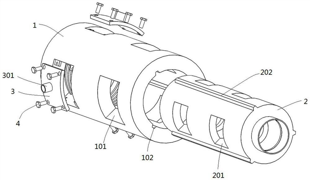
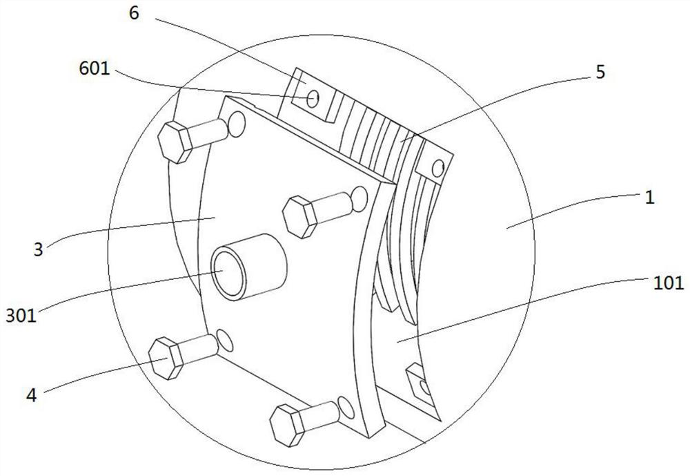
[0024] Embodiment 1: see Figure 1-2 , the integrated flue of the hot blast stove, including an outer flue 1 and an inner lining 2, one end of the outer flue 1 is provided with a smoke inlet pipe 10, and a plurality of installation holes 101 are distributed around the shell of the outer flue 1, each Filter screens 5 are arranged in the installation holes 101 , and the outer ports of the installation holes 101 are detachably connected with the dust removal cover 3 , and the outer surface of the dust removal cover 3 is provided with a connecting pipe 301 .

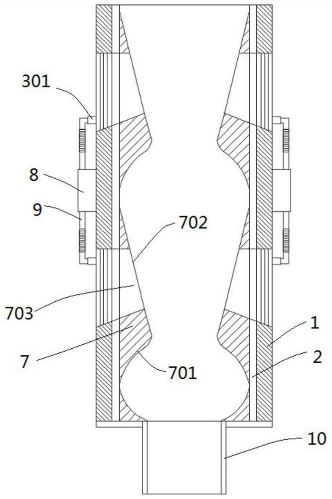
[0025] The inner lining 2 is installed and fixed on the inner wall of the outer flue 1, and the shell of the inner lining 2 is distributed with gaps 201 corresponding to the installation holes 101, and the inner wall of the inner lining 2 is fixed with a number of dust blocking blocks 7 along the circumferential direction. The dust block 7 is annular and cylindrical, and the side of the inner wall of the dust blocking block ...

Embodiment 2

[0027] Example 2: see figure 1 , figure 2 , image 3 , Figure 4 , the integrated flue of the hot blast stove, including an outer flue 1 and an inner lining 2, one end of the outer flue 1 is provided with a smoke inlet pipe 10, and a plurality of installation holes 101 are distributed around the shell of the outer flue 1, each Filter screens 5 are arranged in the installation holes 101 , and the outer ports of the installation holes 101 are detachably connected with the dust removal cover 3 , and the outer surface of the dust removal cover 3 is provided with a connecting pipe 301 .

[0028] The inner lining 2 is installed and fixed on the inner wall of the outer flue 1, and the shell of the inner lining 2 is distributed with gaps 201 corresponding to the installation holes 101, and the inner wall of the inner lining 2 is fixed with a number of dust blocking blocks 7 along the circumferential direction. The dust block 7 is annular and cylindrical, and the side of the inner ...


PUM


Abstract

The invention discloses an integrated flue of a hot blast heater. The integrated flue comprises an outer flue body and an inner lining. One end of the outer flue body is provided with a smoke inlet pipe. A plurality of installing holes are circumferentially distributed in a shell of the outer flue body. A filter screen is arranged in each installing hole. An ash cleanup cover plate is detachably connected with an outer port of each installing hole. A communicating pipe is arranged on the outer surface of each ash cleanup cover plate. The inner lining is fixedly installed on the inner wall of the outer flue body. Notches corresponding to the installing holes are distributed in a shell of the inner lining. A plurality of dust blocking pieces are circumferentially fixed to the inner wall of the inner lining and each in an annular cylindrical shape. The side, close to the smoke inlet pipe, of the inner wall of each dust blocking piece is a flow guide face, and the side, away from the smokeinlet pipe, of the inner wall of each dust blocking piece is a dust accumulating face. Connecting holes are formed in the dust accumulating faces and correspond to the notches in the inner lining oneto one. A dust collector is fixedly installed on the outer wall of the outer flue body. The integrated flue is convenient to install and detach and long in service life and can effectively collect smoke dust in smoke.

Description

technical field [0001] The invention relates to the field of hot blast stoves, in particular to an integrated flue for hot blast stoves. Background technique [0002] At present, the hot blast stove is the most common energy conversion equipment in people's life and industry. It converts the chemical energy or electric energy of conventional energy into heat energy, and the energy is supplied to the corresponding equipment in the form of hot air. It is often used in dryers, dryers, Forming machines and heating etc. In industrial production, hot blast stoves usually use coal as the main energy fuel. With the increasing shortage of coal resources, countries around the world are vigorously developing and innovating biomass combustion and utilization technologies to solve various problems caused by the energy crisis in the future. Due to the high calorific value of coal and less volatile matter, the structure of the coal furnace is relatively simple. The hot stove using bioma...

Claims


Application Information

Patent Timeline
Patent Type & Authority Patents(China)
IPC IPC(8): F23J11/00F23J13/02F23J15/02
CPCF23J11/00F23J13/02F23J15/025
Inventor 杨锴
Owner ANHUI JINSHANG MACHINERY MFG CO LTD
Why Eureka
Try Eureka