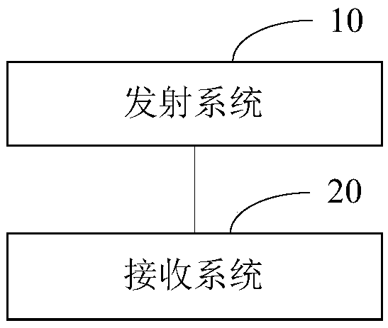
Laser radar system

A lidar and laser technology, applied in the field of distance measurement, can solve the problems of low receiving efficiency and cumbersome structure, and achieve the effects of simplified structure, high response speed, enhanced stability and operability

Inactive Publication Date: 2020-01-21
TANWAY TECH (BEIJING) CO LTD
View PDF5 Cites 1 Cited by
  • Summary
  • Abstract
  • Description
  • Claims
  • Application Information

AI Technical Summary

Problems solved by technology

[0004] In view of this, the present invention proposes a laser radar system to solve the problems of short-distance blind spots, cumbersome structure and low receiving efficiency in the single-line laser radar in the related art

Method used


Image

  • Laser radar system
  • Laser radar system
  • Laser radar system

Examples


Embodiment Construction

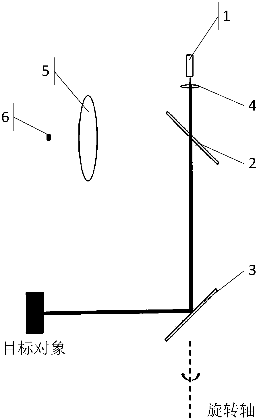
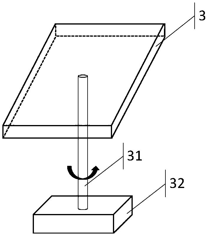
[0033] Various exemplary embodiments, features, and aspects of the invention will be described in detail below with reference to the accompanying drawings. The same reference numbers in the figures indicate functionally identical or similar elements. While various aspects of the embodiments are shown in drawings, the drawings are not necessarily drawn to scale unless specifically indicated.

[0034] The word "exemplary" is used exclusively herein to mean "serving as an example, embodiment, or illustration." Any embodiment described herein as "exemplary" is not necessarily to be construed as superior or better than other embodiments.

[0035] The terminology used in the present invention is for the purpose of describing particular embodiments only and is not intended to limit the invention. As used herein and in the appended claims, the singular forms "a", "the", and "the" are intended to include the plural forms as well, unless the context clearly dictates otherwise. It sho...


PUM


Abstract

The invention relates to a laser radar system. The laser radar system comprises a transmitting system, wherein the transmitting system comprises a laser transmitting part, a first reflecting mirror, and a second reflecting mirror; the laser transmitting part is used for transmitting laser; the first reflecting mirror is provided with a through hole; after the laser penetrates the first reflectingmirror through the through hole, a first light beam is formed and is shot at the second reflecting mirror; the second reflecting mirror is used for receiving the first light beam; after the first light beam passes the second reflecting mirror, the direction of the first light beam is deflected to form a second light beam; and the second light beam is shot at a target object. The demand for the area of the photosensitive surface of a light detecting component and the receiving field of view is reduced by combining the transmitting system and a receiving system of the laser radar system of the embodiment of the invention, which is beneficial to reducing the introduction of background light; the relatively high response speed is obtained; and the problem that a laser radar is close to a rangeblind zone can be effectively solved.

Description

technical field [0001] The invention mainly relates to the technical field of distance measurement, in particular to a laser radar system. Background technique [0002] The technical principle of lidar mainly includes triangulation method, TOF (Time Of Flight, time of flight) method and phase method. Among them, the laser radar using the TOF method continuously emits laser pulses to the target object, and then receives the light returned from the target object through the sensor, and determines the distance of the target object through the round-trip flight time of the laser pulse. The TOF method is most widely used in single-line lidar. [0003] In related technologies, single-line lidar refers to radar in which the laser beam emitted by a laser source is a single line. Single-line LiDAR is capable of tracking the movement of a single object. At present, single-line lidar is widely used in military, automotive, robotics and navigation. For example, single-line lidar can...

Claims


Application Information

Patent Timeline
Patent Type & Authority Applications(China)
IPC IPC(8): G01S17/08G01S7/481
CPCG01S7/481G01S17/08
Inventor 王世玮孟玉凰郑睿童沈罗丰
Owner TANWAY TECH (BEIJING) CO LTD
Why Eureka
Try Eureka