A transformer high-voltage incoming line insulation protective sleeve

A technology of insulating protective sleeve and high-voltage incoming line, applied in the direction of transformer/inductor coil/winding/connection, transformer/inductor parts, electrical components, etc. Easy to fix, easy to install and disassemble, easy to use

Active Publication Date: 2020-10-16
戴文忠
View PDF7 Cites 1 Cited by
  • Summary
  • Abstract
  • Description
  • Claims
  • Application Information

AI Technical Summary

Problems solved by technology

[0002] The transformer safety shield can effectively prevent all kinds of exposed joints from interphase short circuit or grounding caused by various reasons, such as wet flash, pollution flash, salt spray chemical gas corrosion, human contact, small animals or sundries, etc. , Damage to electrical equipment, electric shock and other accidents, the transformer safety shield thus ensures the safe operation of the electrical equipment. The existing transformer shield is usually provided with a strip-shaped through hole on the side wall of the shield to facilitate the insertion of the high-voltage bushing of the transformer. It is fixed in the protective sleeve, and adapts to the insertion of high-voltage bushings of different sizes through the change of the through-hole width at the strip-shaped through-hole during the insertion process of the high-voltage bushing of the transformer, and then fixes the strip-shaped through-hole with screws to realize high-voltage protection. The compression and fixation of the casing prevents the insulating protective sleeve from coming out, but the use of screws during the fixing process requires constant adjustment of the position of the screws when plugging in, and the corresponding threads of the screws on both sides after the two sides of the strip-shaped through hole are stretched The position of the hole changes, making it difficult for the screw to snap in

Method used


Image

  • A transformer high-voltage incoming line insulation protective sleeve
  • A transformer high-voltage incoming line insulation protective sleeve
  • A transformer high-voltage incoming line insulation protective sleeve

Examples


Embodiment Construction

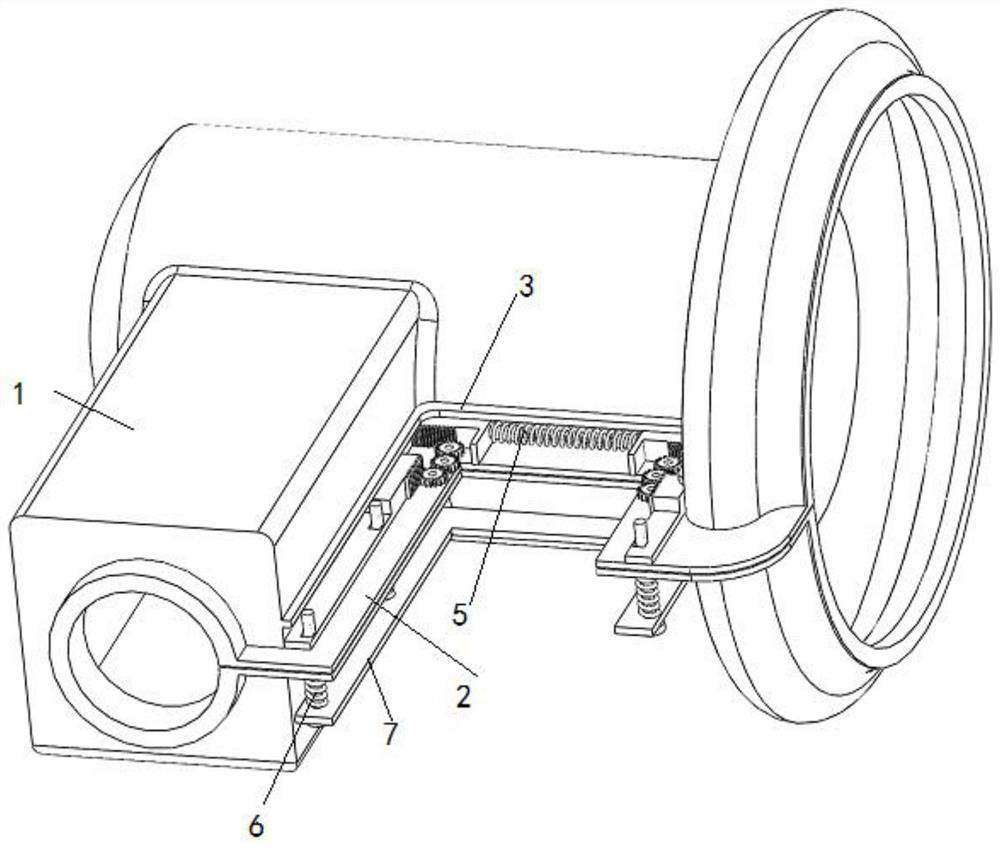
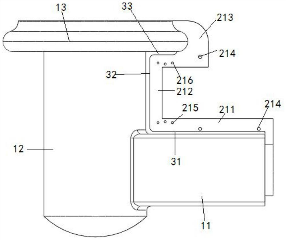
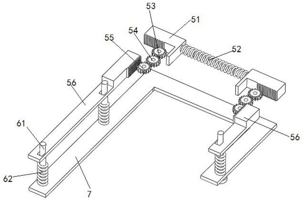
[0029] A transformer high-voltage incoming line insulation protective cover, the protective cover is made of silicone rubber, such as figure 1 As shown, it includes a protective cover body 1 and two oppositely arranged joint parts 2 arranged in the middle part of the side wall of the protective cover body 1. At the same time, the side wall of the protective cover body 1 is provided with a sliding clamping part 3, and the sliding clamping part 3 is connected with the An elastic power mechanism 5 is slidably installed between the joint parts 2, and several locking pieces 6 are installed on the joint part 2 at the same time. When locking, one end of the locking piece 6 passes through the joint part 2 and is locked in the elastic power mechanism 5. The power mechanism 5 limits and fixes the locking piece 6 to realize the fixing of the joint part 2 , and at the same time, several locking pieces 6 are connected and fixed through the push-pull plate 7 .

[0030] Such as figure 2 an...


PUM


Abstract

The invention discloses a high-voltage incoming line insulation protective sleeve of a transformer. The protective sleeve comprises a protective sleeve body and two oppositely-arranged combination parts arranged in the middle of the side wall of the protective sleeve body. Meanwhile, a sliding clamping part is arranged on the side wall of the protective sleeve body, and an elastic power mechanismis installed between the sliding clamping part and the combination parts in a sliding mode; a plurality of locking parts are installed on the combination parts, and the locking parts are connected andfixed through push-pull plates. The protective sleeve is provided with an elastic power mechanism, and two rack plates and three gears in the elastic power mechanism act together, so the movement ofthe two rack locking plates on the two sides is realized; the two rack locking plates are clamped and fixed with the locking pieces after moving to a certain position, clamping and fixing are convenient, only the two rack locking plates need to act on the two rack plates during dismounting, and the two rack locking plates can be dismounted by directly pulling out the locking pieces at the same time through the push-pull plate after moving to a certain position, so the mounting and dismounting are convenient.

Description

technical field [0001] The invention belongs to the field of electric power protective cover preparation and relates to an insulating protective cover for transformer high-voltage incoming lines. Background technique [0002] The transformer safety shield can effectively prevent all kinds of exposed joints from interphase short circuit or grounding caused by various reasons, such as wet flash, pollution flash, salt spray chemical gas corrosion, human contact, small animals or sundries, etc. , Damage to electrical equipment, electric shock and other accidents, the transformer safety shield thus ensures the safe operation of the electrical equipment. The existing transformer shield is usually provided with a strip-shaped through hole on the side wall of the shield to facilitate the insertion of the high-voltage bushing of the transformer. It is fixed in the protective sleeve, and adapts to the insertion of high-voltage bushings of different sizes through the change of the thro...

Claims


Application Information

Patent Timeline
Patent Type & Authority Patents(China)
IPC IPC(8): H01F27/32H01F27/00
CPCH01F27/00H01F27/324
Inventor 戴文忠
Owner 戴文忠
Why Eureka
Try Eureka