
Novel charger transformer

A technology of chargers and transformers, applied in the field of transformers, can solve the problems of overheating of transformers, unsolved electrical safety problems, and accidents caused

Inactive Publication Date: 2020-01-21
关军
View PDF0 Cites 1 Cited by
  • Summary
  • Abstract
  • Description
  • Claims
  • Application Information

AI Technical Summary

Problems solved by technology

[0002] The transformer of the charger is generally a high-frequency transformer, which uses the switch of the triode to control the on-off of the current in the coil, thereby inducing an electromotive force in the secondary, rectifying it through a high-speed diode, and providing the required energy for the load after being filtered by a capacitor, while the transformer As a voltage device for electronic equipment, it mainly plays a role in reducing voltage for electronic equipment, and different transformers correspond to equipment with different output currents. Once the output current of electronic products changes, the transformer must be replaced accordingly, but household electronic products The requirements for the transformer in the application are not high. In order to save costs, a transformer is often used in different electronic products. The mismatch between the output current of the transformer and the product will easily cause the transformer to become seriously hot during use. Electrical safety If the problem is not solved, it may even cause an accident. Based on the above premise, this case developed a new type of charger transformer to solve this problem

Method used


Image

  • Novel charger transformer
  • Novel charger transformer
  • Novel charger transformer

Examples


Embodiment

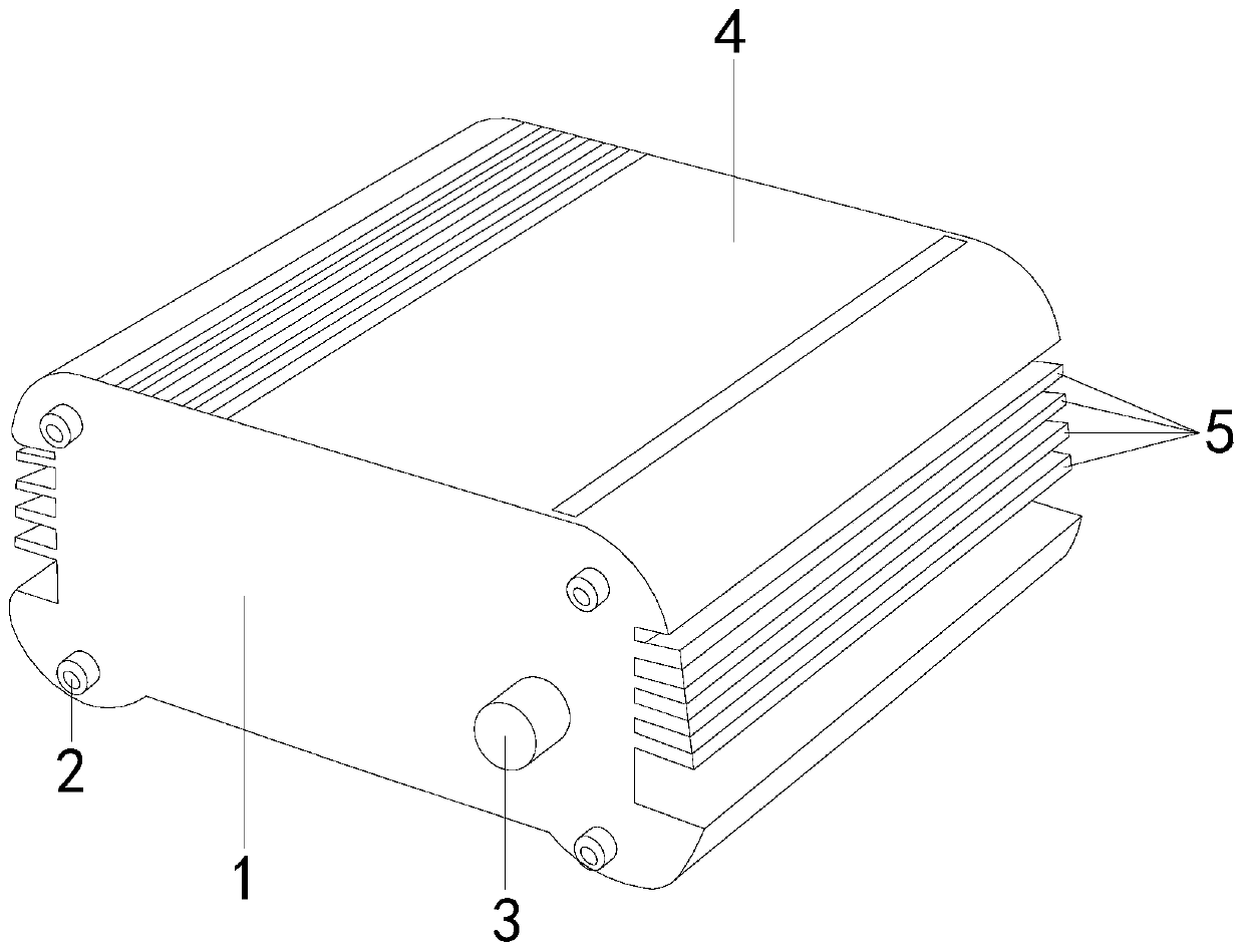
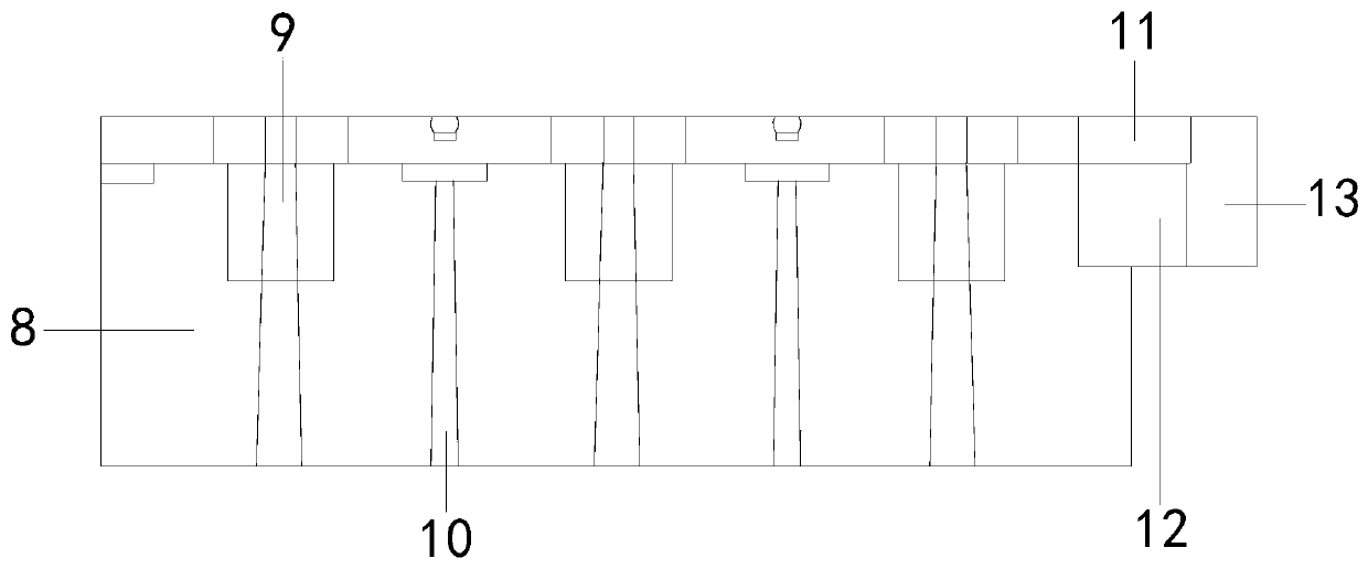
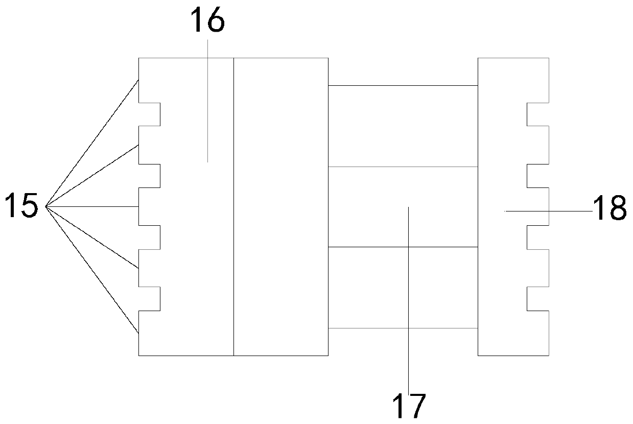
[0022] see figure 1 , the present invention provides a new type of charger transformer, the structure of which includes: a housing 1, bolts 2, a series parallel current device 3, a capacitor 4, and a reinforcing rib 5, the housing 1 is provided with a bolt 2, a series parallel current device 3 It is installed in the shell 1 and connected with it, the capacitor 4 is connected with the series parallel current device 3, and the reinforcing rib 5 is arranged on both sides of the shell 1, and the shell 1 is the shell structure of the transformer, which is made of insulating and waterproof materials, and has the characteristics of insulation and waterproof The high sealing performance can effectively protect the internal components of the transformer. The bolts 2 are installed on both sides of the shell 1, and there are eight bolts in total. They are mainly connected to the shell 1 through thread fitting to enhance the firmness of the structural connection, and at the same time incr...


PUM


Abstract

The invention discloses a novel charger transformer, which structurally comprises a shell, bolts, a series parallel flow device, a capacitor and reinforcing ribs. The novel charger transformer has thefollowing beneficial effects: the problem is solved by structurally arranging the series parallel flow device, a series adjustment type current adjusting element is connected in series between an unstable input voltage end and a stable output voltage end, and the output voltage is kept unchanged through the change of the equivalent resistance; a special elastic structure of a trigger column is driven by pressing to change the number of current interactions, and the output voltage of the current is changed according to different numbers of current interactions; the emergency stop of the deviceis controlled by a brake to prevent the current from being unstable; and through a series current, the voltage of the transformer can be equal to the voltage of an electronic product to which the transformer is applied, and electrical safety accidents caused by excessive heating of the electronic product are avoided.

Description

technical field [0001] The invention relates to the field of transformers, in particular to a novel charger transformer. Background technique [0002] The transformer of the charger is generally a high-frequency transformer, which uses the switch of the triode to control the on-off of the current in the coil, thereby inducing an electromotive force in the secondary, rectifying it through a high-speed diode, and providing the required energy for the load after being filtered by a capacitor, while the transformer As a voltage device for electronic equipment, it mainly plays a role in reducing voltage for electronic equipment, and different transformers correspond to equipment with different output currents. Once the output current of electronic products changes, the transformer must be replaced accordingly, but household electronic products The requirements for the transformer in the application are not high. In order to save costs, a transformer is often used in different ele...

Claims


Application Information

Patent Timeline
Patent Type & Authority Applications(China)
IPC IPC(8): H01F27/40H01F29/00
CPCH01F27/40H01F29/00H01F2027/408
Inventor 关军
Owner 关军
Learn More