Quick locking structure for filter element

A locking structure and filter element technology, applied in fixed filter element filters, filtration separation, chemical instruments and methods, etc., can solve the problems of low visibility, potential safety hazards, troublesome disassembly and assembly, etc. The effect of using the experience

Pending Publication Date: 2020-01-24
GUANGDONG WAPU TECH CO LTD
View PDF5 Cites 5 Cited by
  • Summary
  • Abstract
  • Description
  • Claims
  • Application Information

AI Technical Summary

Problems solved by technology

When a water purifier with a vertical filter element is installed under the kitchen, due to the small vertical space under the kitchen, the line of sight is blocked when replacing the filter element, and the degree of visualization is low. Due to the limited space, the operable space is also small, making the replacement of the filter element extremely difficult. Inconvenient; for water purifiers with fewer and higher filter bottles, the filter bottles of the vertical water purifier and the whole machine have a higher center of gravity and poor stability; When the filter element is vertically arranged, the water inlet a

Method used


Image

  • Quick locking structure for filter element
  • Quick locking structure for filter element
  • Quick locking structure for filter element

Examples


Embodiment 1

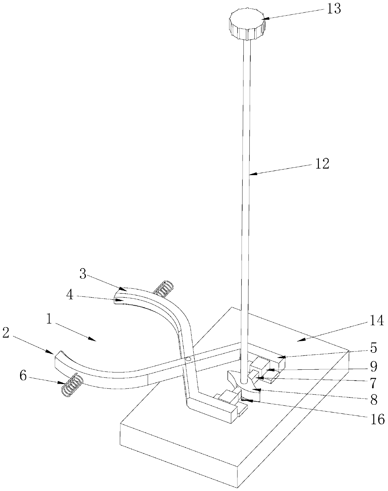
[0037] like Figure 1~4 As shown, the quick locking structure of the filter element in Embodiment 1 includes a locking assembly and a locking space 1 , and the filter element can be installed and locked in the locking space 1 . The locking assembly includes a clamping part, an elastic part and a toggle part, wherein,

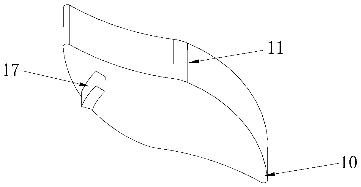
[0038] The clamping part includes two locking strips 2, which are arranged symmetrically with respect to the locking space 1 and which are mutually rotatably connected, and the mutual rotation of the locking strips 2 is parallel to The axial direction of the filter element; one end of the two locking strips 2 is provided with a locking end 3 located in the circumferential direction of the locking space 1, the locking end 3 can move relative to the locking space 1 and the two locking ends 3 are symmetrically arranged relative to the locking space 1, The locking end 3 is provided with an extrusion surface 4 that can contact and squeeze the circumferential side of...

Embodiment 2

[0048] The difference between this embodiment 2 and embodiment 1 is that in this embodiment 2, if Figure 5 As shown, the quick locking structure for the filter element also includes an ejection assembly, which is connected with the filter element and generates a force for the filter element to break away from the locking assembly. Specifically, the ejection assembly includes a contact part 20 and an ejection part 21, wherein,

[0049] The contact part 20 can move axially along the filter core relative to the locking space 1; in this embodiment 2, the contact part 20 is a sleeve part, and guide holes arranged along the filter core axial direction are arranged in the sleeve part, and the sleeve The top of the piece is connected with the filter element;

[0050] The ejection part 21 is a spring, and the ejection part 21 is installed in the guide hole, and when the filter element penetrates into the locking space 1, the contact part 20 presses the ejection part 21, and the eject...


PUM


Abstract

The invention discloses a quick locking structure for a filter element. The quick locking structure comprises a locking assembly and a locking space, the locking assembly comprises a clamping part, anelastic part and a shifting part; the clamping part is provided with a locking end, the locking end can move relative to the locking space, and the locking end is provided with an extrusion surface which can be in contact with and extrude the circumferential side surface of the filter element; the elastic part is connected with the clamping part and enables the locking end to extend into the locking space; when the filter element penetrates into the locking space, the locking end extrudes the elastic part, and the elastic part generates force towards the locking end to move towards the filterelement located in the locking space; the shifting part is connected with the clamping part and can rotate automatically relative to the locking space; the shifting part can rotate relative to the locking space, so that the locking end can move relative to the locking space, and the extrusion surface extrudes or is separated from the circumferential side surface of the filter element. The quick locking structure has the advantages of realization of rapid installation and rapid unlocking of the filter element, simple and convenient operation and the like.

Description

technical field [0001] The invention relates to the field of water purification equipment, in particular to a quick locking structure for a filter element. Background technique [0002] Nowadays, the pollution of water resources is becoming more and more serious, and the problem of urban water safety is particularly serious. In view of the secondary pollution of tap water and the presence of harmful substances in tap water due to source water pollution, more and more households use water purifiers to filter water, making water purifiers one of the ubiquitous household appliances in daily life . The water purifier purifies the water through the filter element, but as the use time prolongs, the impurities in the water will block the filter element, so it needs to be removed and washed or replaced regularly to ensure the normal operation of the water purifier. [0003] The filter bottle fixing methods of existing water purifiers are mostly threaded or quick-connected. When r...

Claims


Application Information

Patent Timeline
IPC IPC(8): B01D29/96B01D35/30
CPCB01D29/96B01D35/306
Inventor 沈鑫白晓峰冯永刚
Owner GUANGDONG WAPU TECH CO LTD
Why Eureka
Try Eureka