
Wind conveying spray gun capable of achieving dust suppression and haze removal

A technology of dust suppression and haze removal and air delivery, which is applied in the field of air delivery spray guns, urban cooling operations, and large-area spray dust removal and haze removal. , increase or decrease the number of nozzles, and enhance the effect of atomization range

Pending Publication Date: 2020-01-24
重庆嘉天环保工程有限公司
View PDF0 Cites 1 Cited by
  • Summary
  • Abstract
  • Description
  • Claims
  • Application Information

AI Technical Summary

Problems solved by technology

[0004] 1. The water mist generated after pressurization hinders the airflow, causing the high-speed wind energy and the sprayed water energy to cancel each other out, resulting in high power and high power consumption of the equipped jet fan;
[0005] 2. The gradually expanding air duct reduces the wind speed and reduces the spray distance. It is necessary to increase the air supply volume to meet the air supply distance requirements, resulting in a large diameter of the air outlet of the fog gun machine, large air volume, high water consumption, and serious waste of resources;
[0006] 3. The atomization direction of the spray device is fixed, and the vehicle-mounted fog cannon machine adopts car transportation and manual operation to change the atomization direction, which has high labor costs, and can only carry out dust suppression operations on roads and low altitudes, with a narrow scope of application
[0007] In addition, the fog cannon machine uses a high-power jet fan. The jet fan has a unique structure, which makes it impossible to silence the air inlet and outlet of the air cylinder. The operation noise is large and the people are seriously disturbed.

Method used


Image

  • Wind conveying spray gun capable of achieving dust suppression and haze removal
  • Wind conveying spray gun capable of achieving dust suppression and haze removal
  • Wind conveying spray gun capable of achieving dust suppression and haze removal

Examples


Embodiment 1

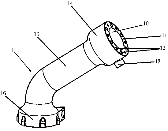
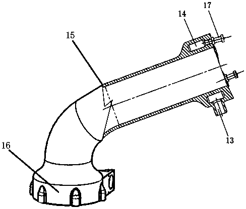
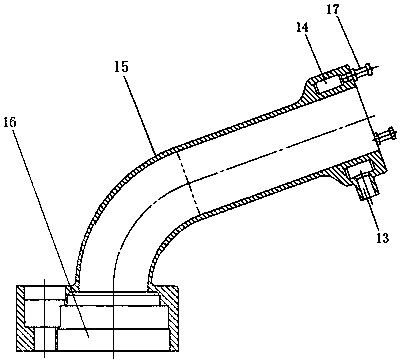
[0036] This example figure 1 with figure 2 Shown, spray gun 1 comprises air cylinder 15, and air cylinder 15 is an elbow, and the lower end of air cylinder 15 is swivel joint 16, and the top of air cylinder 15 is air outlet 10, and spray device is housed at air outlet, and water inlet pipe 13 Connect to the spray unit.

[0037] The spraying device receives the pressurized water entering from the water inlet pipe 13, and sprays water mist. The high-speed airflow of the air outlet 10 of the fan cylinder is in the same direction as the sprayed water mist, forming the superposition of two energies of wind energy and sprayed water energy, which overcomes the problem of water mist. The obstruction of the fog to the airflow, the blowing distance of the water mist increases, or the power of the fan is reduced accordingly.

[0038] Because the air cylinder 15 is an elbow, the rotary joint 16 can realize the spray device installed at the air outlet of the air cylinder to rotate aroun...

Embodiment 2

[0045] Such as Figure 4 with Figure 5 As shown, the difference between this embodiment and Embodiment 1 is that: the water supply ring 14 is arranged on the inner ring of the air cylinder 15, and the water supply ring 15 is composed of the inner wall of the air cylinder, the reducing pipe 19 and the top sealing plate 11. The spraying device adopts the variable diameter pipe 19 in the air outlet 10, which can improve the wind speed, increase the kinetic energy, and make the water mist spray farther.

[0046] Image 6 with Figure 7 It is a further improvement to the present invention: the edge of the air outlet 10 is evenly distributed with silencing serrations 20, and the silencing serrations 20 are used to reduce the eddy current generated by the air outlet and reduce the noise at the outlet of the spray gun. In this embodiment, three atomizing nozzles 17 are evenly distributed along the circumference of the top sealing plate 11 .

Embodiment 3

[0048] Such as Figure 8 with Figure 9As shown, the difference between this embodiment and Embodiment 1 is that the spray device includes an atomizing nozzle and a nozzle connecting seat 18, the center of the air outlet 10 is provided with a nozzle connecting seat 18, and the atomizing nozzle 17 is installed on the nozzle connecting seat 18, and the air duct The front end side wall of 15 is equipped with the water inlet guide pipe 13 that connects flexible pipe, and water inlet guide pipe 13 is communicated with nozzle connection seat 18 by internal aperture. The high-pressure water directly enters the atomizing nozzle 17 installed in the center of the air outlet through the water inlet pipe 13 .

[0049] The inner tube of the air outlet 10 is a diameter reducing pipe 19, which is conducive to improving the wind speed, increasing kinetic energy, and making the water mist spray farther. The edge of the air outlet 10 can also be provided with sound-absorbing serrations to red...


PUM


Abstract

The invention discloses a wind conveying spray gun capable of achieving dust suppression and haze removal. The wind conveying spray gun capable of achieving dust suppression and haze removal comprisesa wind cylinder (15), the wind cylinder (15) is a bent pipe, the lower end of the wind cylinder (15) is a rotation joint (16), an air outlet (10) is formed in the top of the wind cylinder (15), a mist spraying device is arranged on the air outlet, a water inlet leading pipe (13) communicates with the mist spraying device, a rotating mechanism (2) an a connecting pipe (3) are included, the lower bottom end of the connecting pipe (3) is a connecting flange, a straight pipe on the upper segment of the connecting pipe (3) is inserted into a main connector of the rotation joint (16), and the rotation joint (16) is assembled with the rotating mechanism (2). The wind conveying spray gun has the advantages that after an atomizing nozzle is arranged, water mist can be blown following the wind, wind energy and injection water energy are subjected to superposition, under the equal wind condition, the water mist blowing distance is prolonged, under the same blowing distance, the wind amount is small, the water consuming amount is small, and the energy consumption is greatly reduced.

Description

technical field [0001] The invention belongs to the technical field of environmental treatment, and in particular relates to an air-driven spray gun, which is especially suitable for large-area spray dust removal and haze removal, and urban cooling operations. Background technique [0002] With the rapid development of industry, people's living standards and quality of life requirements are increasing day by day, a large number of urban populations gather, forest vegetation is cut down, air pollution is becoming more and more obvious, cities are also covered with a layer of dust, and industrial waste gas is discharged in large quantities, which is common Smog and sandstorms make the city always gray, affecting traffic safety, people's daily travel and health. The existing dust suppression and haze removal systems mostly use atomized water, and the effects of dust suppression, haze removal, and temperature reduction can be achieved in a wide range through water atomization. ...

Claims


Application Information

Patent Timeline
Patent Type & Authority Applications(China)
IPC IPC(8): B05B12/08B05B12/18B05B13/04B01D47/06
CPCB01D47/06B05B12/08B05B12/18B05B13/0405
Inventor 熊佑豪钟旭张明举
Owner 重庆嘉天环保工程有限公司
Learn More