
Passenger train framework side frame welding positioning tooling

A technology for welding positioning tooling and railway passenger cars, which is applied in the direction of welding equipment, auxiliary welding equipment, welding/cutting auxiliary equipment, etc., and can solve the problem of lack of positioning reference objects in the main load-bearing frame structure, high labor intensity for operators, and inconvenient storage management and other problems, to achieve the effect of reducing calibration surveying and mapping work, improving overall work efficiency, and simplifying workload

Active Publication Date: 2020-01-24
CRRC CHANGCHUN RAILWAY VEHICLES CO LTD
View PDF7 Cites 29 Cited by
  • Summary
  • Abstract
  • Description
  • Claims
  • Application Information

AI Technical Summary

Problems solved by technology

[0005] In order to solve the existing side beam manufacturing method, it is necessary to use a large number of screw-type positioning clamps to accurately position each vertical rib, transverse rib and two cap tubes from the three coordinate axes, not only the screw-type positioning clamps are very large , the cost is high, it is not convenient for storage management, and the positioning adjustment process requires repeated calibration and clamping, resulting in high labor intensity for the operator and low positioning efficiency; and the lack of easy-to-measure positioning reference objects on the main load-bearing frame structure, resulting in installation When the clamp is positioned, it is necessary to measure the length of the load-bearing main frame in order to calculate and obtain the position of its midpoint, and then to determine the technical problem of the positioning centerline and mid-vertical plane of the load-bearing main frame structure on the machine tool. The present invention provides a Welding positioning tool for side beam of railway passenger car frame

Method used


Image

  • Passenger train framework side frame welding positioning tooling
  • Passenger train framework side frame welding positioning tooling
  • Passenger train framework side frame welding positioning tooling

Examples


Embodiment Construction

[0053] In order to facilitate the understanding of the present invention, the present invention will be described more fully and in detail below in conjunction with the accompanying drawings and preferred embodiments, but the protection scope of the present invention is not limited to the following specific embodiments.

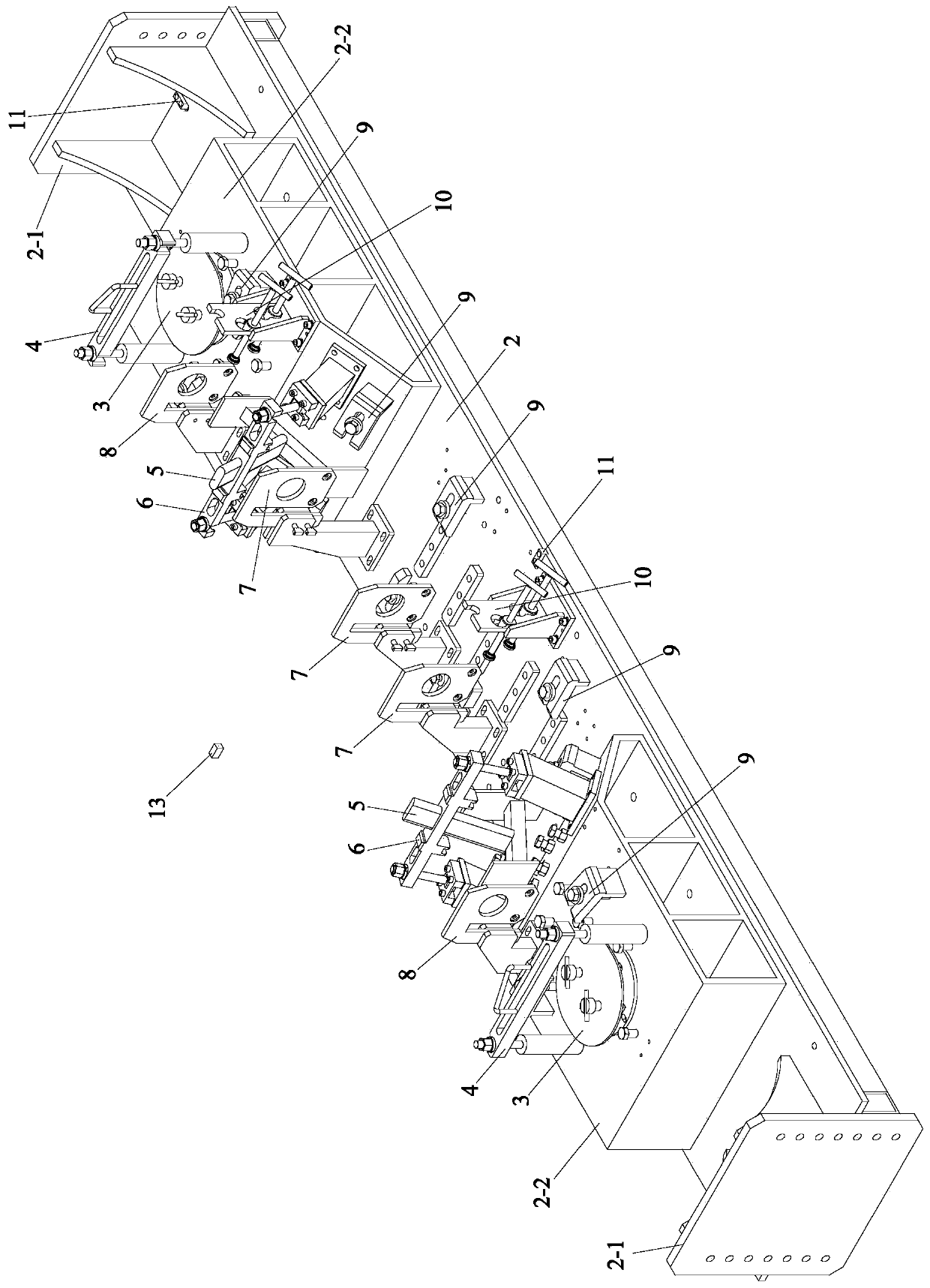
[0054] like Figure 3 to Figure 13 As shown, the railway passenger car frame side beam welding positioning tool of the present invention includes a base 2, two cap barrel centering mechanisms 3, two cap barrel pressing mechanisms 4, two inclined-plane vertical rib positioning mechanisms 5, two vertical plate pressure Tightening mechanism 6, three plane vertical rib positioning mechanisms 7, two horizontal rib positioning mechanisms 8, multiple lower cover pressing mechanisms 9, two vertical plate side tightening mechanisms 10, four reference positioning blocks 11, and a lower cover Plate positioning block press clamp 12 and a lower cover plate positioning blo...


PUM


Abstract

The invention provides a passenger train framework side frame welding positioning tooling, and belongs to the field of bogie welding of railway vehicles. The tooling includes a base, two cap tube centering mechanisms, two cap tube compacting mechanisms, two inclined plane stud positioning mechanisms, two vertical plate compacting mechanisms, three plane stud positioning mechanisms, two transversebar positioning mechanisms, a plurality of lower cover plate compacting mechanisms, two vertical plate lateral jacking mechanisms, four reference positioning blocks, a lower cover plate positioning block pressing pincer and a lower cover plate positioning block. According to the invention, the work load of the welding procedure of a side frame lower cover plate assembly is simplified, the operation difficulty in vertical plane calibration and deformation after welding is directly reduced, the overall working efficiency is improved; and the calibration mapping required for positioning adjustment is reduced, so that the labor intensity is reduced, the precision in assembly positioning is improved, and the production efficiency is improved.

Description

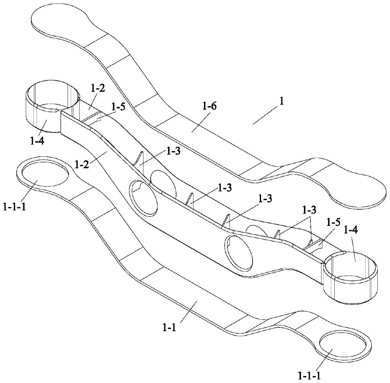
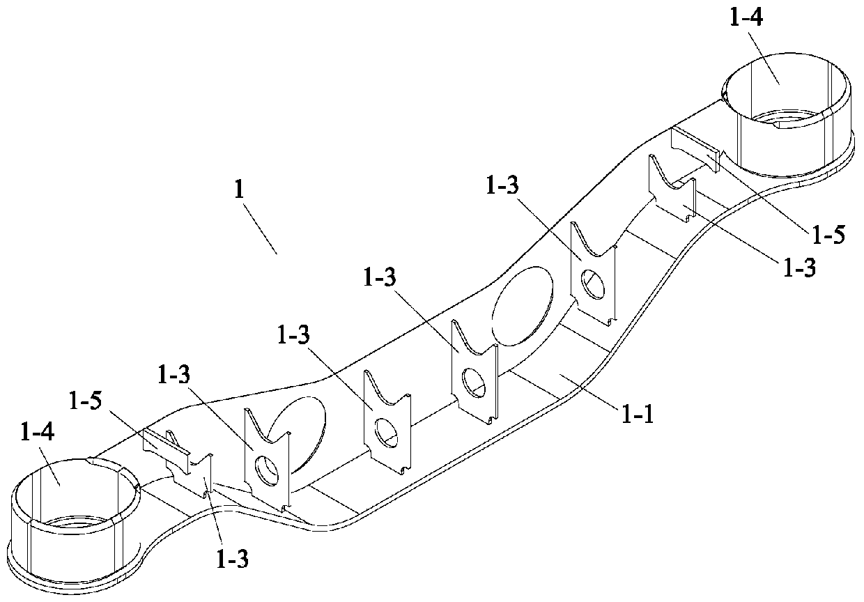
technical field [0001] The invention belongs to the field of rail vehicle bogie welding, and in particular relates to a welding positioning tool for the frame side beam of a railway passenger car. Background technique [0002] The vertical plane is a vertical plane passing through the central axis of the bottom surface of the geometric body, which refers to the section that can divide the symmetrical geometric body into two parts of mirror symmetry along the vertical direction. [0003] like figure 1 As shown, the rail vehicle bogie side beam 1 is a box-shaped integral weldment structure similar to the wings of a bird. Its two wing-shaped side sill vertical plates 1-2 are parallel to each other, and are respectively welded and fixedly connected with the corresponding side sill lower cover plates 1-1, thereby forming a load-bearing main frame. Two approximately elliptical cap cylinders 1-4 are symmetrically fixed to the left and right ends of the load-bearing main frame, an...

Claims


Application Information

Patent Timeline
IPC IPC(8): B23K37/04
CPCB23K37/0443B23K2101/28
Inventor 沈洪娟王子栋李业雄
Owner CRRC CHANGCHUN RAILWAY VEHICLES CO LTD
Learn More