A kind of hydraulic system cavitation removal device and method with hydraulic lock

A technology of hydraulic system and removal device, applied in the direction of fluid pressure actuating device, fluid pressure actuating system components, mechanical equipment, etc., can solve the problems of deterioration of fluid flow characteristics, no cavitation removal, hydraulic device noise, etc., Achieve the effect of eliminating air pockets, carrying less tools and investing less personnel

Active Publication Date: 2022-01-14
BEIJING SHOUGANG CO LTD
View PDF0 Cites 0 Cited by
  • Summary
  • Abstract
  • Description
  • Claims
  • Application Information

AI Technical Summary

Problems solved by technology

When cavitation occurs, the flow characteristics of the liquid flow deteriorate, resulting in unstable flow. The cavitation phenomenon will cause noise and vibration in the hydraulic device, and it will also corrode the metal surface.
[0005] Hydraulic systems with hydraulic locks generally have more hydraulic components. When cavitation occurs, it is difficult to judge where the cavitation occurs. Even if the location of the cavitation is determined, there is currently no effective means to eliminate the cavitation.

Method used


Image

  • A kind of hydraulic system cavitation removal device and method with hydraulic lock
  • A kind of hydraulic system cavitation removal device and method with hydraulic lock

Examples


Embodiment 1

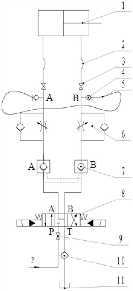
[0031] In an embodiment of the present invention, a hydraulic system cavitation elimination device with a hydraulic lock is applied to a blast furnace hot blast stove hydraulic system. The development of large-scale blast furnace is a manifestation of the improvement of the technical level of the current ironmaking equipment, and it is also an inevitable trend. The enlargement of the blast furnace puts forward new requirements for the equipment in front of the furnace, and the hot blast furnace equipment must also be developed in the direction of large-scale, intelligent and environmental protection in order to meet the production requirements of large blast furnaces. Each blast furnace hot blast stove has about 63 hot blast valves controlled by hydraulic cylinders, and the opening and switching status of these hot blast valves are controlled by the hydraulic system.

[0032] see figure 1 The hydraulic system cavitation elimination device includes a hydraulic cylinder 1, a va...

Embodiment 2

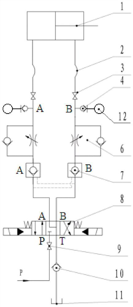
[0038] Based on the same inventive concept, an embodiment of the present invention provides a method for eliminating cavitation in a hydraulic system with a hydraulic lock, and the method is applied to a hydraulic system of a blast furnace hot blast stove.

[0039] see figure 2 , the hydraulic system of the blast furnace hot blast stove includes a hydraulic cylinder 1, a valve 3, a one-way throttle valve 6, a hydraulic lock 7, a reversing valve 8, a main control valve 9, a one-way valve 10 and an oil tank 11. The above-mentioned hydraulic cylinder 1, valve 3. One-way throttle valve 6, hydraulic lock 7, reversing valve 8 and oil tank 11 are sequentially connected through hydraulic oil pipe 2 (high-pressure hose, inner diameter is 20mm), forming a large-flow working hydraulic circuit. The system oil pressure of the hydraulic system P is 12MPa, hydraulic cylinder 1 adopts single-rod double-acting hydraulic cylinder.

[0040] In the hydraulic system of the blast furnace hot blas...


PUM


Abstract

The invention discloses a cavitation removal device and method for a hydraulic system with a hydraulic lock. Two hydraulic oil pipes located between the actuator and the hydraulic lock are provided with connecting devices connected with the hydraulic oil pipes. The device is connected through the cavitation removal pipe. The inner diameter of the cavitation removal pipe is smaller than the inner diameter of the hydraulic oil pipe. A small-flow hydraulic circuit flowing through the hydraulic lock is established through the cavitation removal pipe. Through this small-flow hydraulic circuit, the hydraulic lock can be slowly charged. Oil, eliminates cavitation in the hydraulic system by venting the cavitation air into the tank through the oil return line. The small flow hydraulic circuit lasts for 5 to 10 minutes to eliminate cavitation. The hydraulic system cavitation elimination method of the present invention can quickly deal with the serious impact of cavitation on the hydraulic system, reducing the frequency of troubleshooting for workers, and the hydraulic system cavitation elimination device can be applied to various blast furnaces with hydraulic locks. system with a wide range of applications.

Description

technical field [0001] The application belongs to the technical field of hydraulic systems, and in particular relates to a hydraulic system cavitation elimination device and method with a hydraulic lock. Background technique [0002] Hydraulic systems are widely used in blast furnace metallurgy, automobiles, aerospace and other fields. The hydraulic circuit controls the action of actuators (mainly hydraulic cylinders) to realize functions such as pipeline on-off, loading, unloading, and device movement. After the actuator moves in place, it often needs to be kept for a period of time. For example, when using a hydraulic cylinder for loading, the hydraulic cylinder needs to keep the current position still after the set load is reached. At this time, a hydraulic lock is required. [0003] The hydraulic lock is composed of two interlocking hydraulically controlled one-way valves. The hydraulic circuit can be locked through the hydraulic lock to prevent the flow of oil in the ci...

Claims


Application Information

Patent Timeline
Patent Type & Authority Patents(China)
IPC IPC(8): F15B21/044
CPCF15B21/044
Inventor 邓振月张志宽陈文彬
Owner BEIJING SHOUGANG CO LTD
Why Eureka
Try Eureka