
Clock signal generation circuit and electronic equipment

A clock signal and circuit generation technology, applied in the direction of generating electrical pulses, pulse generation, electrical components, etc., can solve the problems of unstable frequency, high cost of RTC chips, low cost, etc., to improve clock accuracy, meet clock accuracy requirements, The effect of reducing circuit cost

Active Publication Date: 2020-01-24
SEMICONDUCTOR MANUFACTURING INTERNATIONAL (BEIJING) CORP +1
View PDF10 Cites 0 Cited by
  • Summary
  • Abstract
  • Description
  • Claims
  • Application Information

AI Technical Summary

Problems solved by technology

The RTC chip contains a crystal oscillator (crystal). Due to the high price of the crystal oscillator, the cost of the RTC chip is high, and its price remains high.
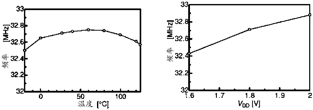
[0003] A ring oscillator (Ring OSCillatior, referred to as ROSC) can also generate a clock signal, but the disadvantage of ROSC is that its oscillation frequency changes with the influence of external factors, the frequency accuracy is low, and the frequency is unstable
The existing ROSC optimization scheme mainly uses Process Voltage Temperature (PVT) sensors to correct the frequency of the ROSC clock signal, but it is difficult for PVT sensors combined with ROSC to provide high-precision frequency, and the clock accuracy cannot reach millions. One part (1part per million, referred to as 1ppm)
Therefore, in the circuit design of existing electronic equipment, once a high-precision clock signal is required, the more expensive RTC crystal oscillator is still used
[0004] At present, there is a lack of clock signal generation circuits that meet the accuracy requirements and are low in cost

Method used


Image

  • Clock signal generation circuit and electronic equipment
  • Clock signal generation circuit and electronic equipment
  • Clock signal generation circuit and electronic equipment

Examples


Embodiment Construction

[0028] As mentioned in the background technology, the existing clock signal generation circuit can use the RTC crystal oscillator to generate the clock signal, but its price is relatively high; it can also use a ring oscillator (Ring OSCillatior, referred to as ROSC) combined with process, voltage, temperature (Process Voltage Temperature) , referred to as PVT) sensor generates a clock signal, but its clock accuracy is difficult to reach 5ppm, which cannot meet the high precision requirements of some specific electronic devices for clock signals.

[0029] The inventors of the present application have discovered that the ring oscillator is particularly suitable for application in various electronic devices due to its simple structure, low price, and low power consumption. However, since the ring oscillator is not controlled by feedback, the frequency of the output clock signal is easily affected by factors such as process, operating temperature, and power supply voltage, and the...


PUM


Abstract

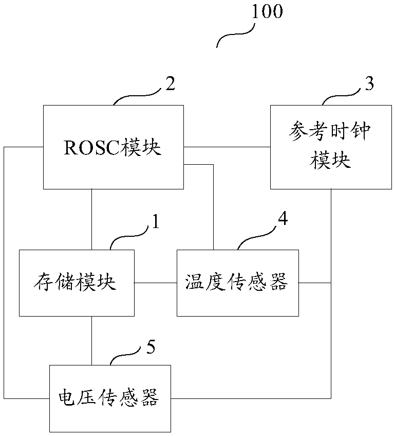
The invention discloses a clock signal generation circuit and electronic equipment, and the circuit comprises: an ROSC module which is suitable for generating a clock signal; areference clock module which is connected with the ROSC module and is suitable for providing a reference clock signal; a temperature sensor which is connected with the ROSC module and is suitable for sensing the temperature;a voltage sensor which is connected with the ROSC module and is suitable for sensing voltage; a storage module which is connected with the temperature sensor, the voltage sensor and the ROSC module and is suitable for storing a basic calibration table, wherein fine adjustment data for temperature and voltage are recorded in the table. When the ROSC module is initialized, the frequency of the clock signal is corrected by utilizing the reference clock signal, otherwise, the ROSC module searches for matched fine adjustment data according to the temperature and the voltage to correct the frequency of the clock signal, and when the search time exceeds a preset threshold value, the reference clock signal is used for correcting the frequency of the clock signal, and the high-precision clock signal generation circuit based on the ring oscillator is low in price.

Description

technical field [0001] The invention relates to the technical field of electronic circuits, in particular to a clock signal generation circuit and electronic equipment. Background technique [0002] In a traditional solution, the clock signal may be generated by a real time clock (Real Time Clock, RTC for short) chip. The RTC chip includes a crystal oscillator (crystal). Because the price of the crystal oscillator is high, the cost of the RTC chip is high, and its price remains high. [0003] A ring oscillator (Ring OSCillatior, referred to as ROSC) can also generate a clock signal, but the disadvantage of ROSC is that its oscillation frequency changes with the influence of external factors, the frequency accuracy is low, and the frequency is unstable. The existing ROSC optimization scheme mainly uses Process Voltage Temperature (PVT) sensors to correct the frequency of the ROSC clock signal, but it is difficult for PVT sensors combined with ROSC to provide high-precision f...

Claims


Application Information

Patent Timeline
Patent Type & Authority Applications(China)
IPC IPC(8): H03K3/011H03K5/135
CPCH03K3/011H03K5/135Y02D10/00
Inventor 杨家奇黄正乙
Owner SEMICONDUCTOR MANUFACTURING INTERNATIONAL (BEIJING) CORP
Learn More