
Beam selection for communicating signals

A technology for transmitting signals and beams, applied in the field of computer program products, which can solve problems such as loss of active links, and achieve the effect of improving reliability and performance

Pending Publication Date: 2020-01-24
TELEFON AB LM ERICSSON (PUBL)
View PDF4 Cites 1 Cited by
  • Summary
  • Abstract
  • Description
  • Claims
  • Application Information

AI Technical Summary

Problems solved by technology

However, if the degradation is too sudden, there will not be enough time to establish and execute the beam search process, which will result in the loss of the active link used for control and data signals between the TRP and the terminal device, thus resulting in the so-called beam link Fault (BLF)
If beam link failures are not properly handled such that the link between the TRP and the end device is not restored within a certain period of time, the end device may experience a Radio Link Failure (RLF)
RLF typically requires protocol layer 3 signaling and introduces both overhead signaling and delay

Method used


Image

  • Beam selection for communicating signals
  • Beam selection for communicating signals
  • Beam selection for communicating signals

Examples


Embodiment Construction

[0029]The inventive concept will now be described more fully hereinafter with reference to the accompanying drawings, in which specific embodiments of the inventive concept are shown. However, inventive concepts may be embodied in many different forms and should not be construed as limited to the embodiments set forth herein; rather, these embodiments are provided by way of example so that this disclosure will be thorough and complete, and will The scope of the inventive concept fully conveys to those skilled in the art. In the description, the same numbers refer to the same elements. Any steps or features shown by dashed lines should be considered optional.

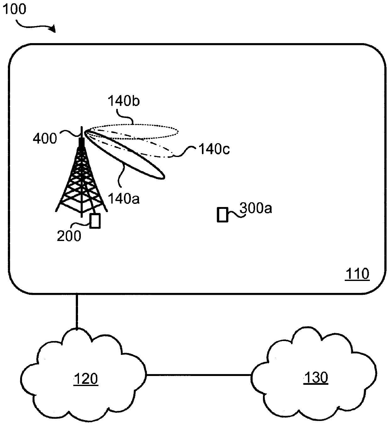
[0030] figure 1 is a schematic diagram illustrating a communication network 100 in which embodiments presented herein may be applied. The communication network 100 may be a third generation (3G) telecommunication network, a fourth generation (4G) telecommunication network, or a fifth generation (5G) telecommunication ...


PUM


Abstract

There is provided mechanisms for adapting which beam to use for communicating signals. A method is performed by a radio transceiver device. The radio transceiver device is capable of communicating thesignals using beams selected from a set of beams. The method comprises communicating signals with another radio transceiver device while using a first beam selected from the set of beams. The methodcomprises detecting that the signals are communicated at decreasing quality level while using the first beam. The decreasing quality level is caused by radio propagation channel deterioration. The method comprises, in response thereto, initiating a switch to a backup beam of the first beam, without performing any beam training, to continue communicating the signals with said another radio transceiver device, thereby adapting which beam to use for communicating the signals.

Description

technical field [0001] Embodiments presented herein relate to a method, a radio transceiver device, a computer program, and a computer program product for which beam is adapted for transmitting a signal. Background technique [0002] In communication networks, it can be challenging to obtain good performance and capacity for a given communication protocol, its parameters, and the physical environment in which the communication network is deployed. [0003] For example, for future generations of mobile communication systems, frequency bands at many different carrier frequencies may be required. For example, low such frequency bands may be required to achieve adequate network coverage for end devices, and higher frequency bands (e.g. at millimeter wavelength (mmW), i.e. near and above 30 GHz) may be required to achieve the required network capacity . Generally speaking, at high frequencies, the propagation characteristics of the radio channel are more challenging and beamfor...

Claims


Application Information

Patent Timeline
IPC IPC(8): H04B7/06H04B7/08
CPCH04B7/088H04B7/0695H04B7/0617H04B7/0632H04W16/28
Inventor A·尼尔松A·雷亚尔
Owner TELEFON AB LM ERICSSON (PUBL)
Learn More