Special vehicle for repairing grabbing arm structure of crane by using wind power

A technology for cranes and special vehicles, which is applied in the directions of cranes, motor vehicles, and vehicles used for freight transportation, can solve the problems that the wheels cannot be rotated, cannot be well shielded from rainwater, and is easy to slide, and achieves the effect of improving stability.

Pending Publication Date: 2020-01-31
维尔力德(徐州)工程机械技术研究院有限公司
View PDF0 Cites 2 Cited by
  • Summary
  • Abstract
  • Description
  • Claims
  • Application Information

AI Technical Summary

Problems solved by technology

[0005] The bearing plate is installed movably with the rotating shaft 1 and the movable plate through the shaft sleeve, so that when the special vehicle transports the items to the designated location, the motor drives the rotating shaft 1 to rotate, so that one end of the bearing plate can be tilted downward, which is convenient for the staff to take off the items , which solves the troublesome technical problem when the existing items are removed from the special vehicle;
[0006] 1) By setting the brake plate, when the special vehicle slides down, the brake plate will prevent the rotation of the rollers, thereby making the wheels unable to rotate, which can prevent the special vehicle from sliding downward when moving in mountainous areas. Improve the stability and solve the technical problem that the existing special vehicles are easy to slide when moving in mountainous terrain;
[0007] 2) By setting the rain cloth, when it encounters rainy and snowy weather during transportation, the rain cloth can be covered on the top of the bottom plate by pulling the rope, which can effectively prevent the items from being wet by rain, and solve the existing problem that cannot be well Technical problems of ground sheltering rainwater

Method used


Image

  • Special vehicle for repairing grabbing arm structure of crane by using wind power
  • Special vehicle for repairing grabbing arm structure of crane by using wind power
  • Special vehicle for repairing grabbing arm structure of crane by using wind power

Examples


Embodiment Construction

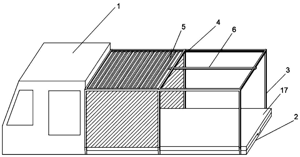
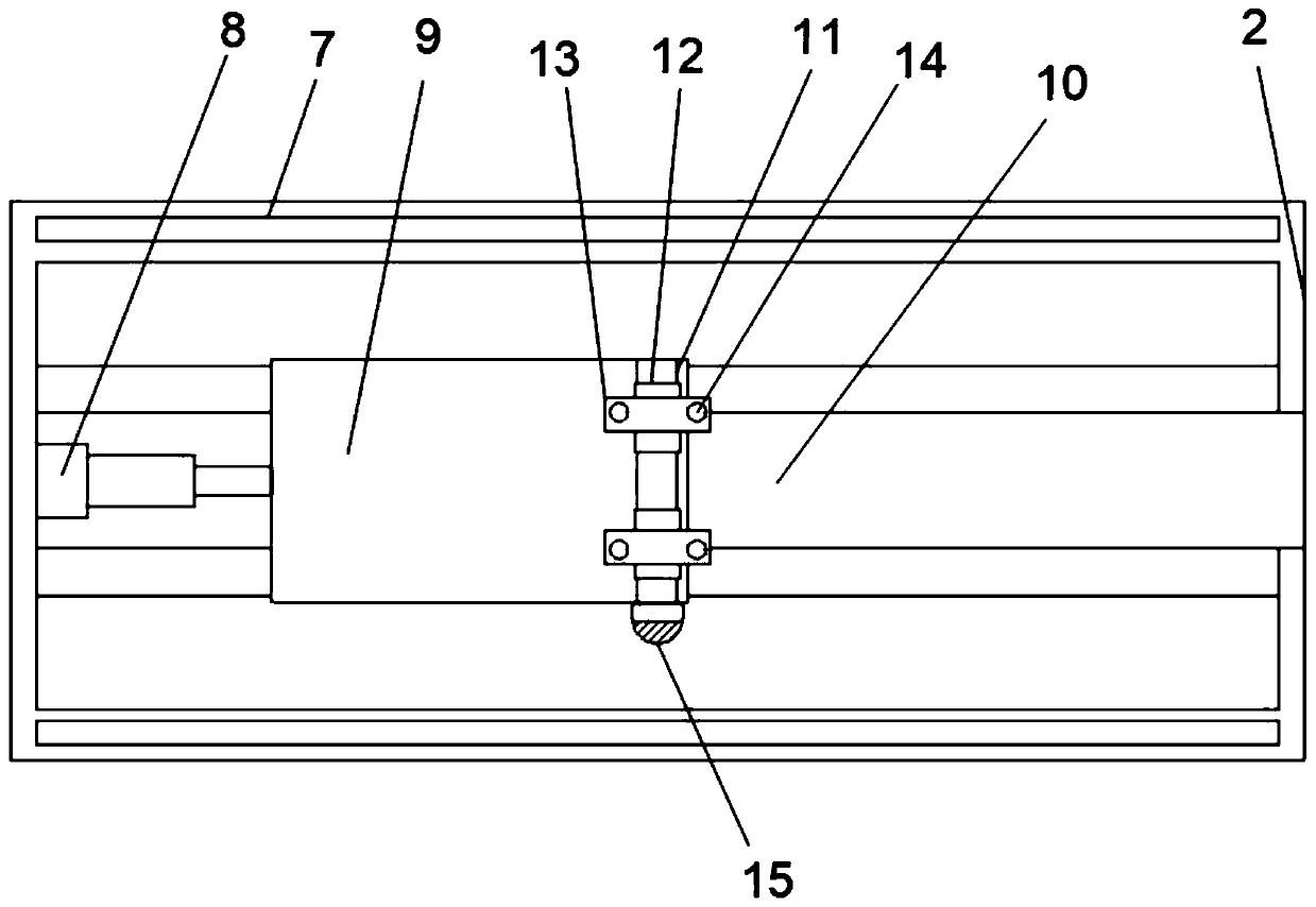
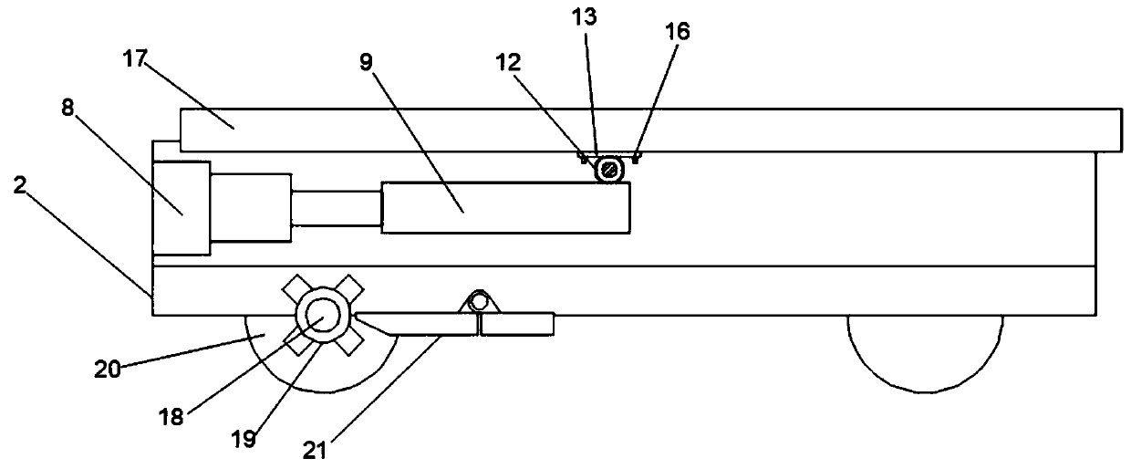
[0025] Such as Figure 1-4 As shown, a special vehicle with a holding arm structure for a wind power maintenance crane includes a main body 1. A bottom plate 2 is provided at the right end of the main body 1 near the lower end. The bottom plate 2 is provided with a bracket 3, and the inner wall of the bracket 3 is provided with The fixed groove 4 is provided with a rain cloth 5, the right end of the rain cloth 5 is provided with a rope 6 near the middle position, and the upper surface of the bottom plate 2 is provided with a chute 7 near the front and rear ends. The inner left side wall of the bottom plate 2 is provided with a hydraulic telescopic rod 8, the right end of the hydraulic telescopic rod 8 is provided with a movable plate 9, and a chute 2 10 is opened between the movable plate 9 and the bottom plate 2. The upper end of the movable plate 9 A rotating shaft 11 is arranged near the right end, a shaft sleeve 12 is arranged on the rotating shaft 11, a mounting plate 13 i...


PUM


Abstract

The invention discloses a special vehicle for repairing a grabbing arm structure of a crane by using wind power. The special vehicle comprises a main body; the position, close to the lower end, of theright end of the main body is provided with a base plate; a bracket is arranged on the base plate; the inner sidewalls of the bracket are each provided with a fixing slot; each fixing slot is internally provided with rain shielding cloth; the part, close to the middle position, of the right end of the rain shielding cloth is provided with a rope; the positions, close to the front and rear ends, of the surface of the upper end of the base plate are each provided with a slide way I; the internal left sidewall of the base plate is provided with a hydraulic telescopic rod; the right end of the hydraulic telescopic rod is provided with a movable plate; a slide way II is formed between the movable plate and the base plate; the position, close to the right end, of the upper end of the movable plate is provided with a rotating shaft I; the rotating shaft I is provided with a shaft sleeve; and the shaft sleeve is provided with a mounting plate. The special vehicle disclosed by the invention can provide conveniences for a worker to taken down an object, can be commendably prevented from sliding down when moving in places such as a mountainous area, improves the stability and can effectivelyprevent the object from being wetted by rainwater.

Description

Technical field [0001] The invention belongs to the field of cranes, in particular to a special vehicle for the arm structure of a wind power maintenance crane. Background technique [0002] Crane refers to a multi-action hoisting machinery that vertically lifts and horizontally transports heavy objects within a certain range, also known as crane, aerial crane and crane; the main feature of the tire crane is: its driving cab and lifting control room are combined First, it is evolved from a crawler crane. It turns the crawler and walking support part of the walking mechanism into a chassis with tires, which overcomes the shortcomings of the crawler crane's crawler plate causing damage to the road surface. It is a material handling machine; the bridge crane is a horizontal frame Lifting equipment used for lifting materials over workshops, warehouses and material yards. Because its two ends are located on tall concrete columns or metal supports, it is shaped like a bridge. The bridg...

Claims


Application Information

Patent Timeline
Patent Type & Authority Applications(China)
IPC IPC(8): B66C23/42B66C23/36B60P7/04
CPCB60P7/04B66C23/36B66C23/42
Inventor 杨慧杰肖华薛振刘威
Owner 维尔力德(徐州)工程机械技术研究院有限公司
Why Eureka
Try Eureka