Circuit breaker test device and breaker utilizing the same

A test device and circuit breaker technology, which is applied to emergency protection devices, circuits, and parts of protective switches, can solve problems such as high cost and complex structure, and achieve the effects of saving costs, simplifying structure, and reducing parts

Pending Publication Date: 2020-01-31
GACIA ELECTRICAL APPLIANCE
View PDF1 Cites 2 Cited by
  • Summary
  • Abstract
  • Description
  • Claims
  • Application Information

AI Technical Summary

Problems solved by technology

[0005] The notification number is CN102194619B, which discloses a test device for a circuit breaker and a circuit breaker with the test device. The structure of the circuit breaker test device includes a test button, a test button spring, a connecting conductor, a lever, and a test resistor. Complicated, it needs to be realized through the transmission lever of mechanical components, and the cost is relatively high

Method used


Image

  • Circuit breaker test device and breaker utilizing the same
  • Circuit breaker test device and breaker utilizing the same
  • Circuit breaker test device and breaker utilizing the same

Examples


Embodiment 1

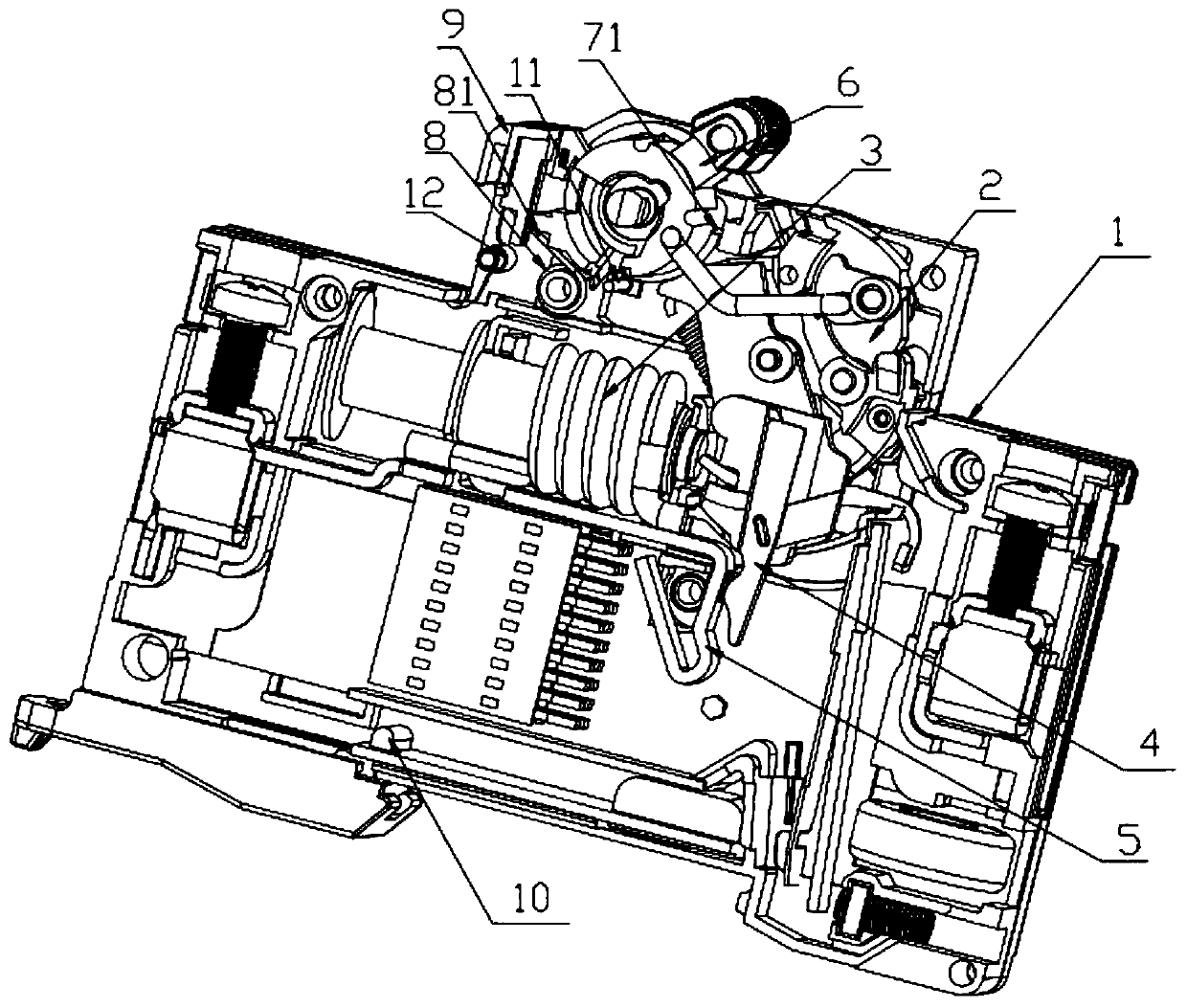
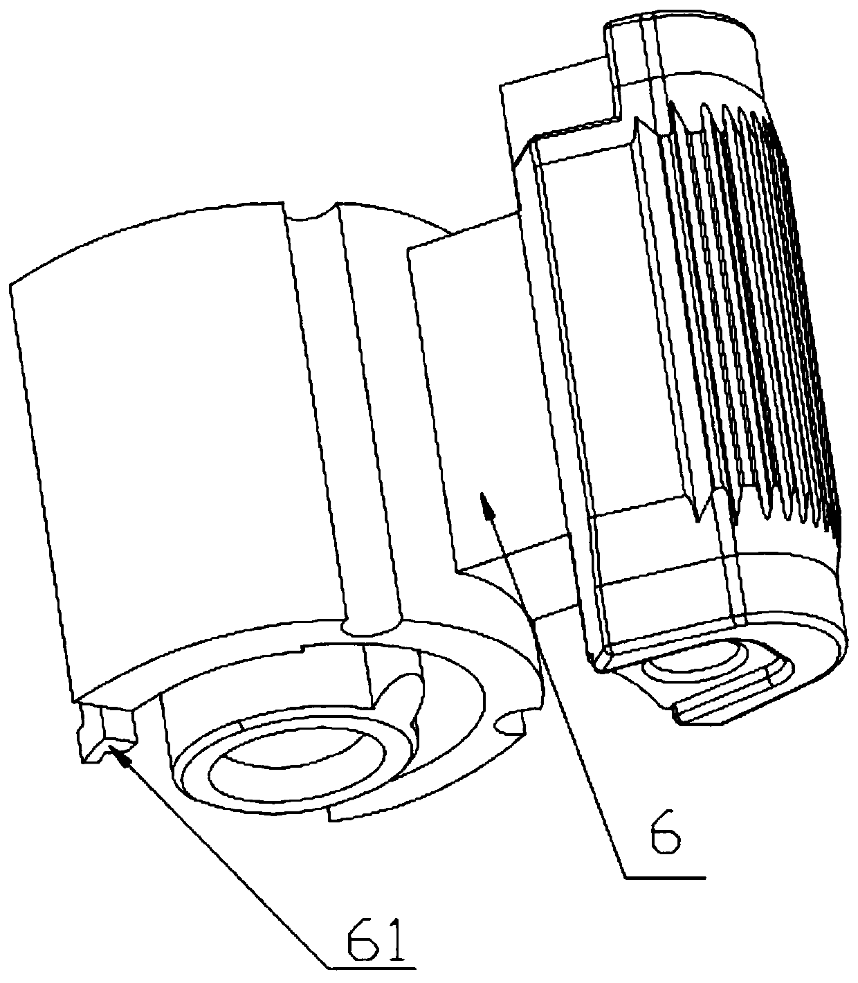
[0017] Such as Figure 1-Figure 4 A circuit breaker is shown, which includes an insulating case 1, a cover (not shown in the figure), a mechanical assembly 2, an earth leakage release 3, a moving contact 4, a static contact 5 and a test device, wherein the moving The contact 4 is connected with the mechanical component 2 through the moving contact bracket. The above mechanisms are all prior art except the test device, which will not be elaborated here. The specific structure of the circuit breaker test device will be introduced in detail below. The circuit breaker test device Including a handle 6, a handle spring 7, a test button spring 8, a test button 9, a connecting conductor, a test resistor 10, a first test contact 11 and a second test contact 12, the handle 6 is movably connected to the shell through a pin shaft, and the handle 6 It is connected to the mechanical component 2 by transmission, and the two ends of the test resistor 10 are respectively connected to the N-lev...

Embodiment 2

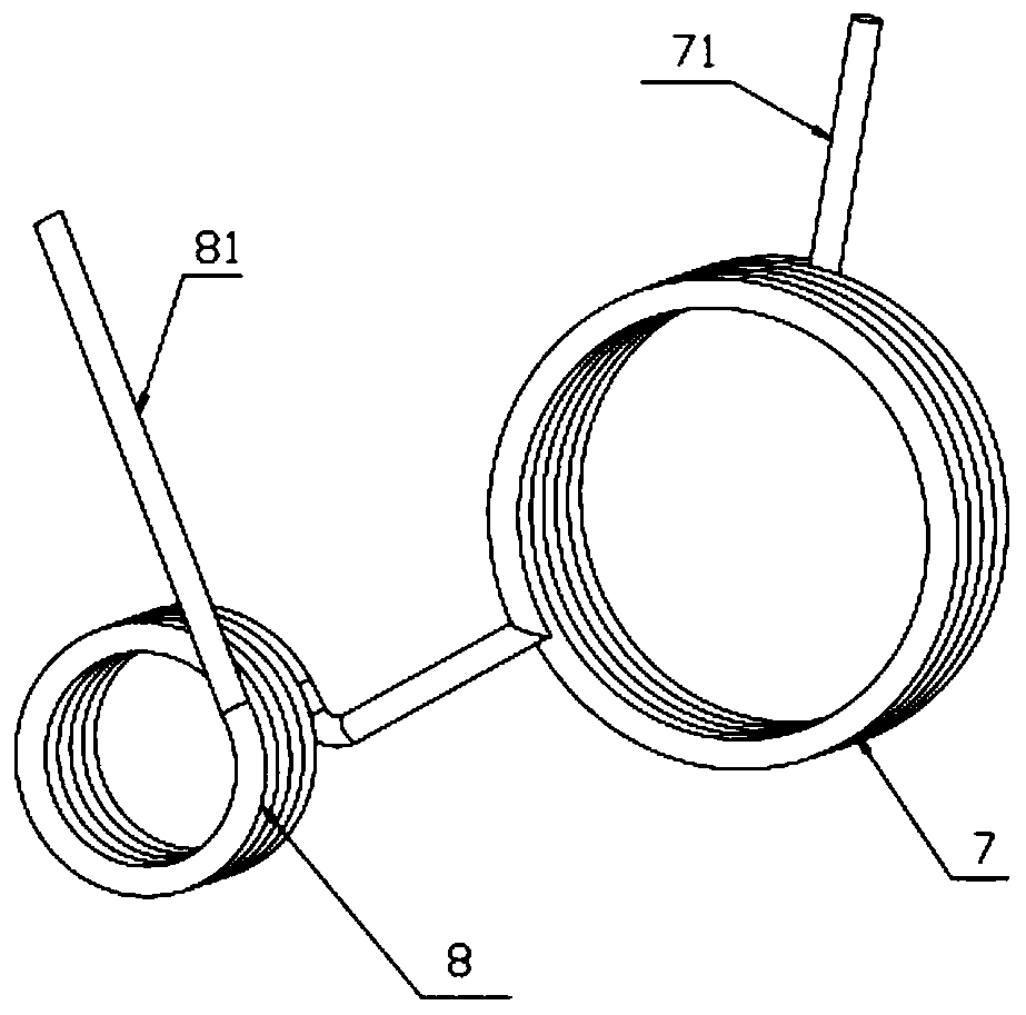
[0020] Such as Figure 5 As shown, the difference between the present embodiment and the first embodiment is that the handle spring 7 and the test button spring 8 are in a split structure, and the handle spring 7 and the test button spring 8 are electrically connected.


PUM


Abstract

The invention provides a circuit breaker test device. The device comprises a handle, a handle spring, a test button spring, a test button, a connecting conductor, a test resistor, a first test contactand a second test contact, wherein the handle spring is at least provided with a movable end, the movable end of the handle spring rotates along with the handle, the test button spring is electrically connected with a handle spring, the movable end of the handle spring abuts against a first test contact after the handle spring is switched on along with rotation of the handle, and the movable endof the handle spring is disconnected from the first test contact after switching off or tripping, so an electric leakage test loop is in a disconnected state. The device is advantaged in that the handle spring is electrically connected with the test button spring, the movable end of the handle spring moves along with the handle, and thereby contact and separation of the handle spring and the firsttest contact are achieved, the structure of a test loop is achieved under the condition that the same purpose can be achieved, the number of parts is reduced, and the cost is saved.

Description

technical field [0001] The invention belongs to the technical field of circuit breakers, in particular to a test device in the circuit breaker. Background technique [0002] With the development of electrical automation, miniature electronic leakage circuit breakers have become an electrical appliance widely used in low-voltage terminal power distribution systems. The function of the leakage circuit breaker is to provide leakage protection and overload protection for the industrial frequency power supply. When there is a power failure such as electric shock or circuit leakage current exceeding the specified value, the leakage circuit breaker can generate tripping and other protection actions in a very short time, automatically cut off the power supply, ensure personal safety, and prevent accidents caused by equipment leakage. Leakage circuit breakers have overload and short-circuit protection functions, which can be used to protect the overload and short-circuit of the line...

Claims


Application Information

Patent Timeline
Patent Type & Authority Applications(China)
IPC IPC(8): H01H83/04H01H71/12
CPCH01H71/128H01H83/04
Inventor 汪联峰谭智超杨鑫
Owner GACIA ELECTRICAL APPLIANCE
Why Eureka
Try Eureka