
Energy storage battery with waterproof function

An energy storage battery and functional technology, which is applied in the direction of secondary batteries, battery pack components, and isolation of batteries from their environment, etc., can solve problems affecting the use effect of lithium batteries, poor waterproof performance of lithium batteries, and reduced service life, etc., to achieve lower temperature , Accelerate the speed of heat dissipation and reduce the effect of safety hazards

Inactive Publication Date: 2020-01-31
风帆(扬州)有限责任公司
View PDF0 Cites 3 Cited by
  • Summary
  • Abstract
  • Description
  • Claims
  • Application Information

AI Technical Summary

Problems solved by technology

[0002] Energy storage batteries mainly refer to batteries used in solar power generation equipment, wind power generation equipment and renewable energy storage energy. The existing energy storage batteries are mainly lithium batteries, and the existing lithium batteries have obvious advantages compared with traditional lead-acid batteries. Advantages, it has a higher energy ratio, a longer service life, a rated weight and a lighter weight, and is more energy-saving and environmentally friendly. However, when a lithium battery is in use, it will generate a lot of heat, which is accumulated in the battery and cannot be dissipated, which affects the use of lithium batteries. effect, reduce the service life, and the waterproof performance of the lithium battery is poor, and the lithium battery itself will be damaged when encountering water flow, and even cause safety hazards. Therefore, we propose an energy storage battery with waterproof function

Method used


Image

  • Energy storage battery with waterproof function
  • Energy storage battery with waterproof function
  • Energy storage battery with waterproof function

Examples


Embodiment Construction

[0017] The following will clearly and completely describe the technical solutions in the embodiments of the present invention with reference to the accompanying drawings in the embodiments of the present invention. Obviously, the described embodiments are only some, not all, embodiments of the present invention. Based on the embodiments of the present invention, all other embodiments obtained by persons of ordinary skill in the art without making creative efforts belong to the protection scope of the present invention.

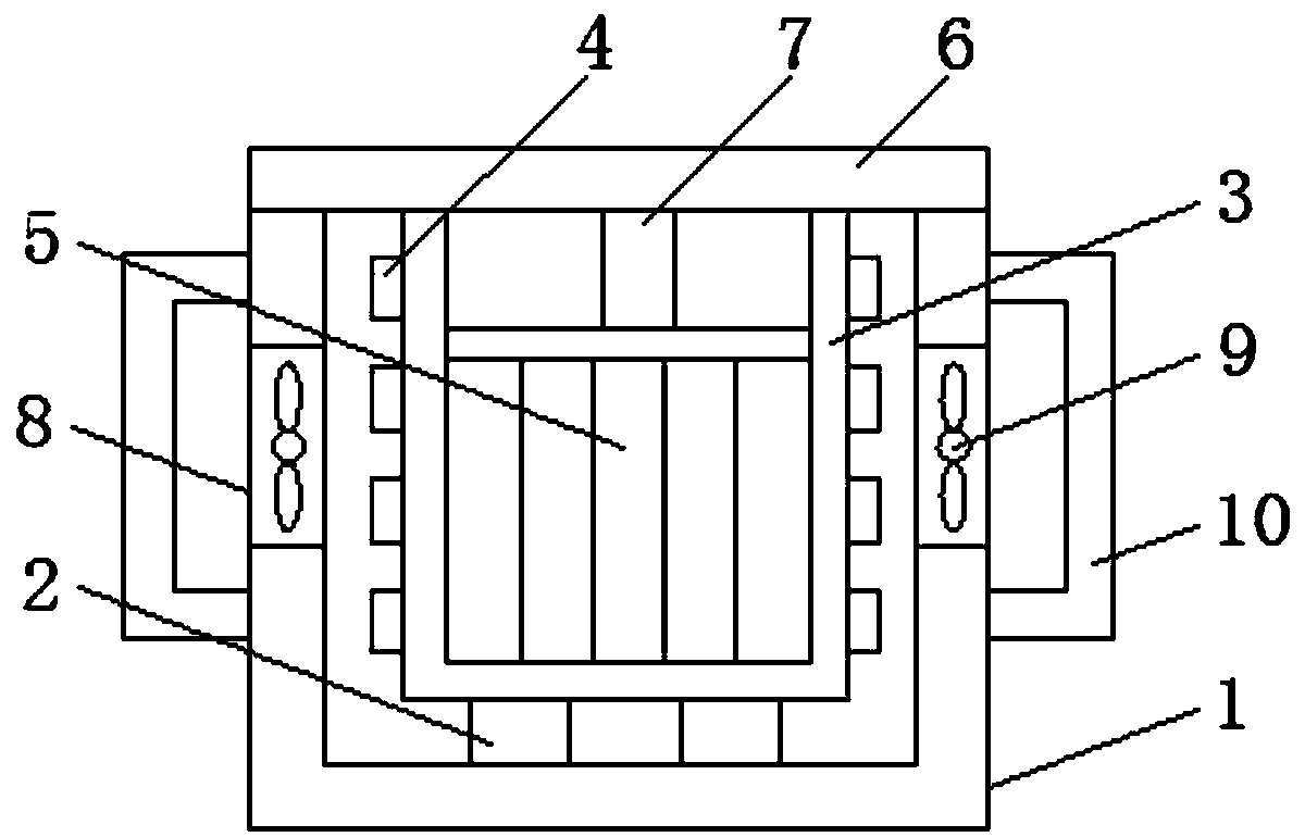
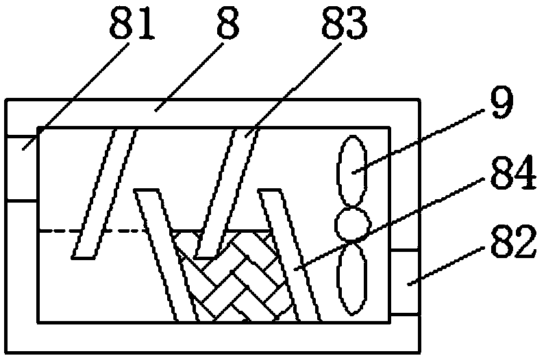
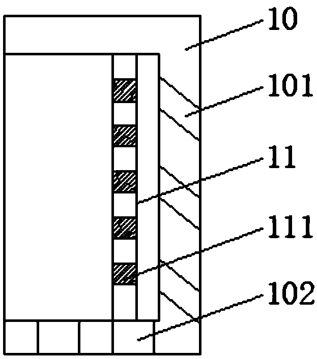
[0018] see Figure 1-3 , the present invention provides a technical solution: an energy storage battery with a waterproof function, including a casing 1, support blocks 2 are provided on the left and right sides of the bottom of the inner cavity of the casing 1, and the tops of two sets of support blocks 2 are connected to the installation box 3, Support the installation box 3, and at the same time separate the installation box 3 from the shell 1, prevent wate...


PUM


Abstract

The invention discloses an energy storage battery with a waterproof function in the technical field of batteries. The battery comprises a casing. The tops of two sets of the support blocks are connected with a mounting box. A battery pack is arranged at the bottom of the inner cavity of the mounting box. The top of the casing is connected with a top cover. A heat dissipation box is arranged in theinner cavity of the mounting cavity. The top of the inner cavity of the heat dissipation box is provided with two sets of first baffles. The bottom of the inner cavity of the heat dissipation box isprovided with two sets of second baffles. A fan is arranged on the inner wall of one side, which is close to the inner cavity of the casing, of the heat dissipation box. Waterproof covers are arrangedon the outer walls of the left and right sides of the heat dissipation box. According to the device, the heat dissipation box is separated from the outside by the waterproof covers, which prevents external water from entering the device from the heat dissipation box; the mounting box is separated from the casing by the support blocks, which further reduces the probability of water flowing into the battery; heat dissipation blocks are arranged on the left and right sides of the mounting box to increase the contact area between the mounting box and the air, which improves the heat dissipation speed.

Description

technical field [0001] The invention relates to the technical field of batteries, in particular to an energy storage battery with a waterproof function. Background technique [0002] Energy storage batteries mainly refer to batteries used in solar power generation equipment, wind power generation equipment and renewable energy storage energy. The existing energy storage batteries are mainly lithium batteries, and the existing lithium batteries have obvious advantages compared with traditional lead-acid batteries. Advantages, it has a higher energy ratio, a longer service life, a rated weight and a lighter weight, and is more energy-saving and environmentally friendly. However, when a lithium battery is in use, it will generate a lot of heat, which is accumulated in the battery and cannot be dissipated, which affects the use of lithium batteries. effect, reduce the service life, and the lithium battery is poorly waterproof, and the lithium battery itself will be damaged when ...

Claims


Application Information

Patent Timeline
Patent Type & Authority Applications(China)
IPC IPC(8): H01M2/10H01M10/613H01M10/6563
CPCH01M10/613H01M10/6563H01M50/20H01M50/24Y02E60/10
Inventor 李刚赵平宋波吴古才柴林李斐
Owner 风帆(扬州)有限责任公司
Learn More