A ball type permanent magnet coupling

A permanent magnet coupling and ball type technology, which is applied in the direction of permanent magnet clutch/brake, electric brake/clutch, electromechanical device, etc., can solve the problems of unstable transmission, high installation accuracy requirements, and coaxial transmission, etc.

Inactive Publication Date: 2020-08-21
SHANDONG UNIV
View PDF3 Cites 0 Cited by
  • Summary
  • Abstract
  • Description
  • Claims
  • Application Information

AI Technical Summary

Problems solved by technology

[0003] The predecessors have designed magnetic couplings with different structures. For example, the patent application number 201210434166.5 discloses a high-performance asynchronous disc magnetic coupling. The magnetic field is distributed along the axial direction, and its transmission torque is small, which cannot be very Coaxial transmission, large axial force and unstable transmission; the patent application number 201020181438.1 discloses a radial permanent magnet magnetic coupling, the magnetic field is distributed along the radial direction, although the axial force is small, the installation accuracy is high And it cannot be non-coaxial transmission; the patent application number 201720671721.4 discloses a magnetic coupling that can realize non-coaxial transmission, but only a universal joint is connected to the magnetic coupling, and its transmission torque is also Small, large axial force, unstable transmission
[0004] In summary, the inventors found that the existing magnetic couplings have the disadvantages of small transmission torque, coaxial transmission, or large axial force and unstable transmission, which limits the scope of use of magnetic couplings and develop

Method used


Image

  • A ball type permanent magnet coupling
  • A ball type permanent magnet coupling
  • A ball type permanent magnet coupling

Examples


Embodiment 1

[0038] Attached below figure 1 - attached Figure 10 The ball type permanent magnet coupling disclosed in this embodiment is further described;

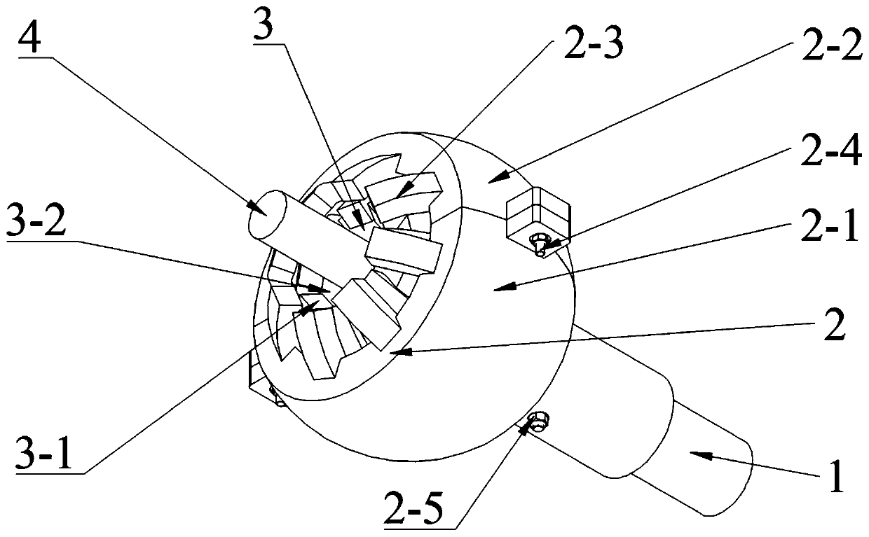
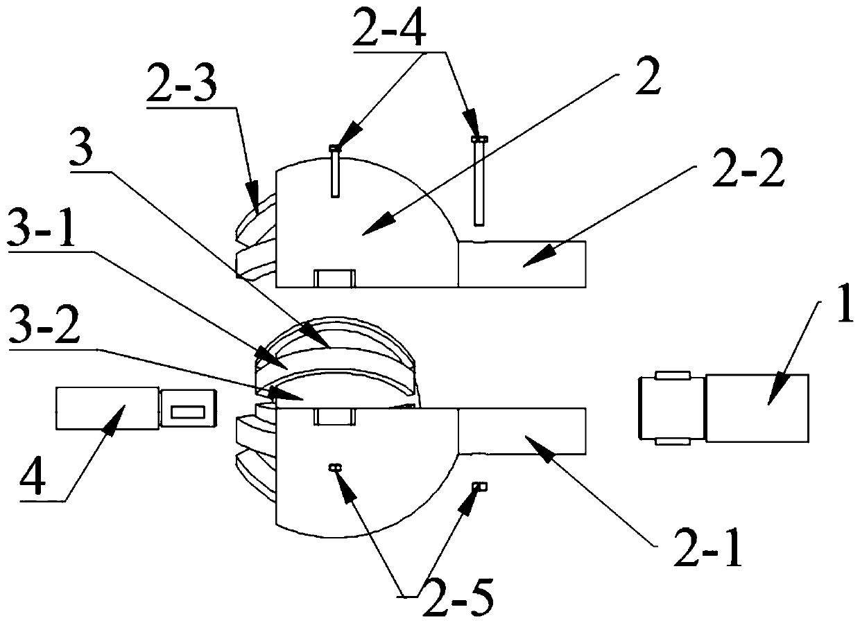
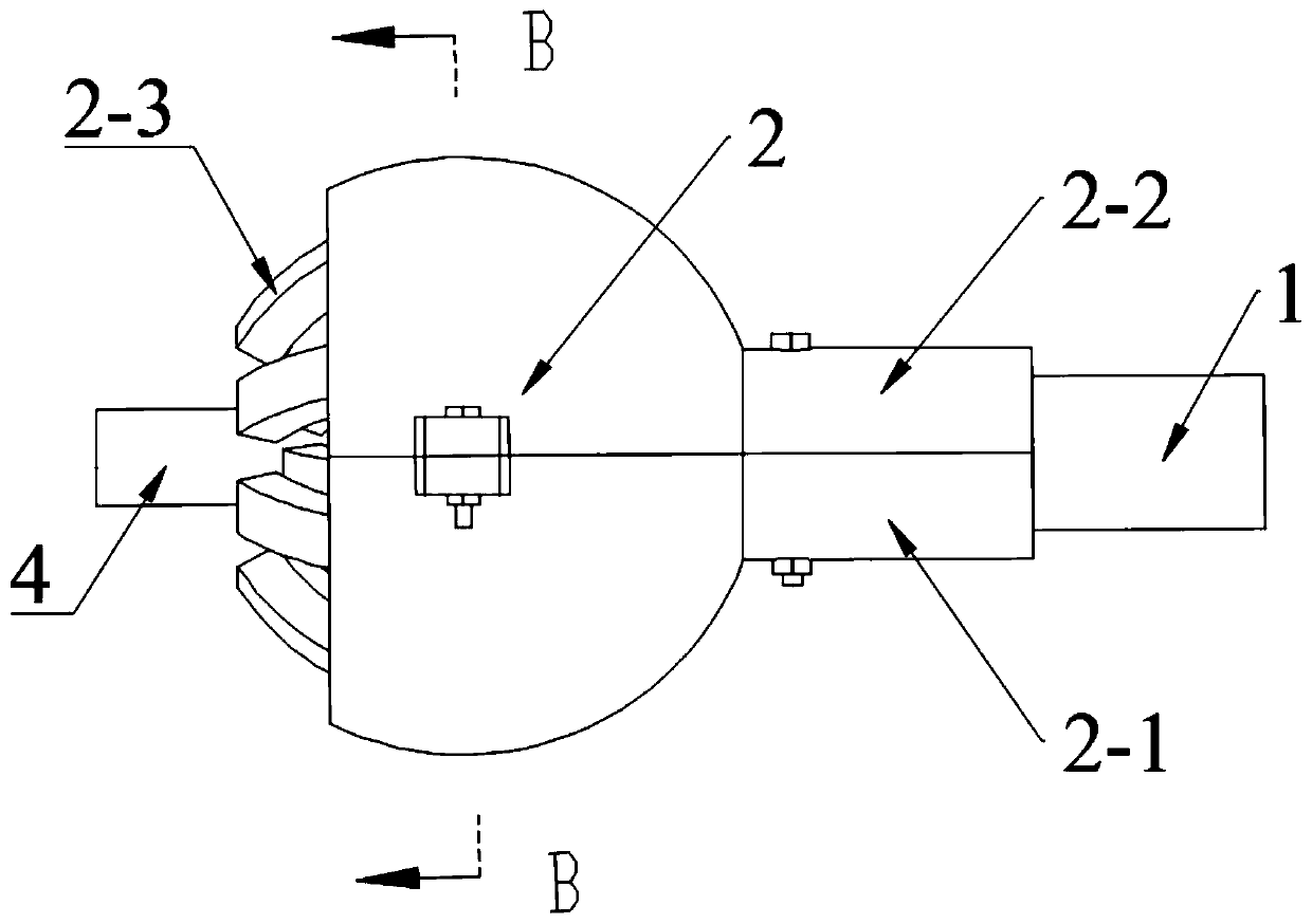
[0039] Refer to attached figure 1 As shown, the ball-type permanent magnet coupling is mainly composed of an outer rotation body 2 at the input end and an inner rotation body 3 at the output end. The outer rotation body 2 is connected to the input shaft 1, and the inner rotation body 3 is connected to the output shaft 4.

[0040] Such as figure 2 As shown, the outer rotor 2 is composed of a hollow spherical outer rotor and an outer rotor magnet. For the convenience of assembly, the outer rotor is divided into upper and lower outer rotors, and the single piece is spoon-shaped. The outer rotor 2-1, the outer rotor 2-2 are relatively arranged, and the outer rotating magnets 2-3 are evenly arranged on the inner surfaces of the outer rotor 2-1 and the outer rotor 2-2;

[0041] Such as Image 6 As shown, the outer rotor includes a se...


PUM


Abstract

The invention discloses a ball permanent magnet coupler which comprises an outer rotating body and an inner rotating body. The outer rotating body is connected with an input shaft and the inner rotating body is connected with an output shaft. The outer rotating body comprises two opposite outer rotors, and the outer rotors are spoon-shaped. The inner rotating body comprises a spherical inner rotor, the inner rotor is wrapped between the two outer rotors. A plurality of outer rotating magnets are embedded in the arc-shaped inner surface of the outer rotors, a plurality of inner rotating magnets are embedded in the spherical surface of the inner rotor, and the outer rotating magnets and the inner rotating magnets attract each other in magnetic force. The outer rotating body and the inner rotating body of the coupler are spherical in shape, and the magnets are arranged on the spherical surfaces of the outer rotors and the inner rotor so that the magnetic field is distributed along the radial direction of the sphere, and the coupler has the remarkable characteristics of large transmission torque, non-coaxial transmission, no axial force and stable transmission.

Description

technical field [0001] The disclosure belongs to the technical field of mechanical transmission couplings, and in particular relates to a ball-type permanent magnet coupling. Background technique [0002] Some industrial production requires non-contact transmission to transmit torque, such as toxic and harmful chemical production, environmental industry and semiconductor industry. The most common non-contact transmission is the magnetic coupling, which is characterized by: it can realize complete sealing and isolation between the input end and the output end; it can limit the torque and realize overload protection; it can realize the soft start of the machine; it has small vibration and small friction. [0003] The predecessors have designed magnetic couplings with different structures. For example, the patent application number 201210434166.5 discloses a high-performance asynchronous disc magnetic coupling. The magnetic field is distributed along the axial direction, and it...

Claims


Application Information

Patent Timeline
Patent Type & Authority Patents(China)
IPC IPC(8): H02K49/10
CPCH02K49/104H02K49/106
Inventor 谢朝阳李学勇
Owner SHANDONG UNIV
Why Eureka
Try Eureka