
Speed-reduction wire winder and dust collector thereof

A cord reel and speed reduction technology, applied in vacuum cleaners, electrical components, cleaning equipment, etc., can solve the problems of easy disconnection of power plug wires, limited power cord speed, easy to throw and hurt users, etc., and achieves low structural strength, Small size and low replacement cost

Pending Publication Date: 2020-02-04
SUZHOU CHUNJU ELECTRIC CO LTD
View PDF0 Cites 0 Cited by
  • Summary
  • Abstract
  • Description
  • Claims
  • Application Information

AI Technical Summary

Problems solved by technology

But there are at least two disadvantages in this way of taking up the wire: during the reset process, the inertia of the coil spring is getting bigger and bigger, resulting in faster and faster take-up speed, and the power plug will be thrown at the take-up mouth every time, making the power supply The internal wire of the plug is easy to disconnect; the speed of winding up the wire is fast and it is easy to hurt the user
So it is necessary to limit the speed when the power line is retracted

Method used


Image

  • Speed-reduction wire winder and dust collector thereof
  • Speed-reduction wire winder and dust collector thereof
  • Speed-reduction wire winder and dust collector thereof

Examples


Embodiment Construction

[0036] Below in conjunction with specific embodiment, content of the present invention is described in further detail:

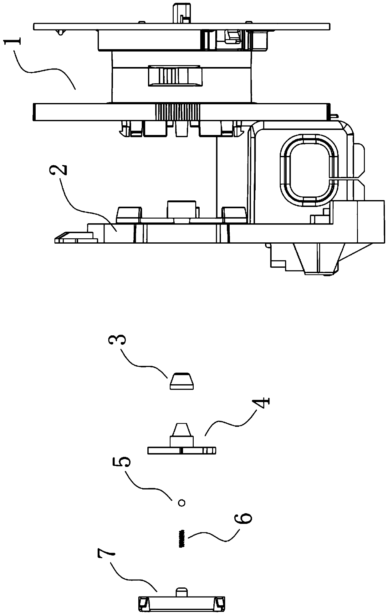
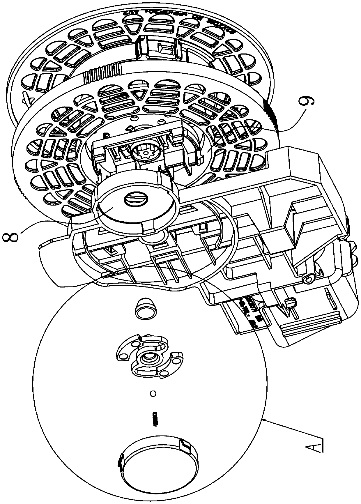
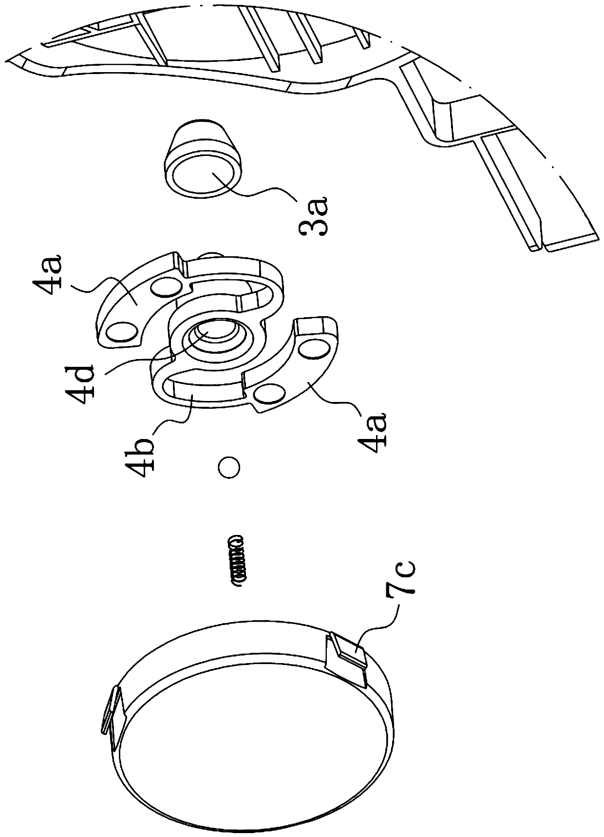
[0037] In order to achieve the purpose of the present invention, a speed-reducing wire reel includes: a winding mechanism, including a winding roller 1 for winding electric wires, and the winding roller 1 is movably connected with a bracket 2 through a rotating shaft 1a; The brake disc 4 connected to the wire roller 1 by transmission, the brake disc 4 rotates synchronously with the winding roller 1, the bracket 2 is provided with a concave circular pit 8, the brake disc 4 is located in the circular pit 8, and the mouth of the circular pit 8 is covered There is a brake disc cover 7; the brake disc 4 is elastically connected with a brake pad 4a, and the radial outward movement distance of the brake pad 4a is positively correlated with the rotational speed of the brake disc 4 until the brake pad 4a contacts the circular pit 8 or the brake disc cover 7 friction....


PUM


Abstract

The invention discloses a speed-reduction wire winder and a dust collector thereof. The speed-reduction wire winder comprises a wire winding mechanism and a speed-reduction mechanism, wherein the wirewinding mechanism comprises a wire winding roller for winding an electric wire; the wire winding roller is movably connected with a support through a rotary shaft; the speed-reduction mechanism comprises a brake disc in transmission connection with the wire winding roller; the brake disc rotates synchronously along with the wire winding roller; a sunk circular pit is arranged on the support; thebrake disc is located in the circular pit; a brake disc cover covers an opening part of the circular pit; a brake pad is elastically connected onto the brake disc; and the radial outward moving distance of the brake pad and the rotating speed of the brake disc are in positive correlation until the brake pad and the circular pit or the brake disc cover are in contact friction. By adopting the speed-reduction wire winder provided by the invention for controlling the speed of the wire winding roller, the wire winding speed is controlled, and the occurrence of the phenomenon that parts are damageddue to excessive high speed is prevented. A centrifugal force is utilized for braking and reducing speed, so that the characteristic of automatic working is realized, and a speed-reduction effect aims at adapting to different speeds of the wire winding roller. The integrated manufacturing cost is low, and the structure is ingenious.

Description

technical field [0001] The invention relates to the field of wire take-up structures of vacuum cleaners, in particular to a speed-reducing wire reel and a vacuum cleaner thereof. Background technique [0002] Household appliances are generally connected with a power cord. In order to facilitate the storage of the power cord when not in use, some power cords are equipped with a cord reel. The existing conventional cord reel utilizes the elastic force of the coil spring to drive the cord reel to rotate, so as to achieve the winding effect of the power cord. But there are at least two disadvantages in this way of taking up the wire: during the reset process, the inertia of the coil spring is getting bigger and bigger, resulting in faster and faster take-up speed, and the power plug will be thrown at the take-up mouth every time, making the power supply The inner wire of the plug is easy to disconnect; the fast speed of the wire is easy to throw and hurt the user. Therefore, i...

Claims


Application Information

Patent Timeline
Patent Type & Authority Applications(China)
IPC IPC(8): A47L9/26A47L9/00
CPCA47L9/00A47L9/26
Inventor 潘先黄
Owner SUZHOU CHUNJU ELECTRIC CO LTD
Learn More