Ball placing mechanism for disc workpieces

A workpiece and ball technology, applied in the field of workpiece processing machinery and equipment, can solve the problems of accurate adjustment to the required position, multi-operation of the driving mechanism, low work efficiency, etc., and achieves stable and accurate placement, reasonable structural design, and improved efficiency and quality. Effect

Active Publication Date: 2020-02-04
临沂威尔森新型材料有限公司
View PDF16 Cites 3 Cited by
  • Summary
  • Abstract
  • Description
  • Claims
  • Application Information

AI Technical Summary

Problems solved by technology

Disc workpieces are commonly used workpieces now. During the production and processing of disc workpieces, the disc workpieces need to undergo processing steps such as die-casting, grinding and drilling in sequence. After the above processing steps, according to the subsequent use of the disc workpiece According to the needs of the disc workpiece, it is necessary to evenly place multiple balls on the outside of the disc workpiece, so that the disc workpiece can realize the role of supporting and rotating during specific use. Placement one by one, the work intensity of the workers is high and the work efficiency is low. The existing ball placement is also com

Method used


Image

  • Ball placing mechanism for disc workpieces
  • Ball placing mechanism for disc workpieces
  • Ball placing mechanism for disc workpieces

Examples


Embodiment Construction

[0021] In order to further describe the present invention, a specific implementation of a ball placement mechanism for a disc workpiece is further described below in conjunction with the accompanying drawings. The following examples are explanations of the present invention and the present invention is not limited to the following examples.

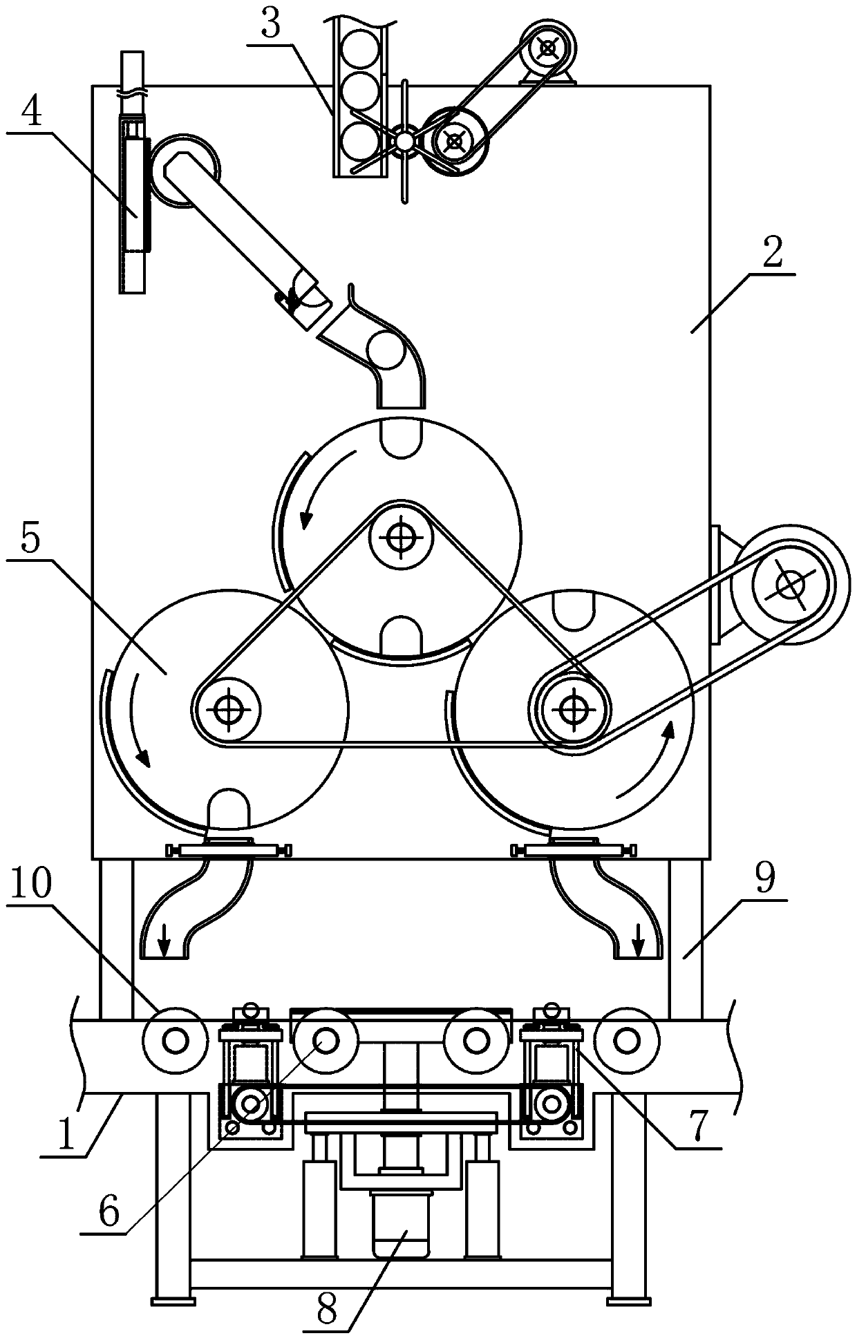
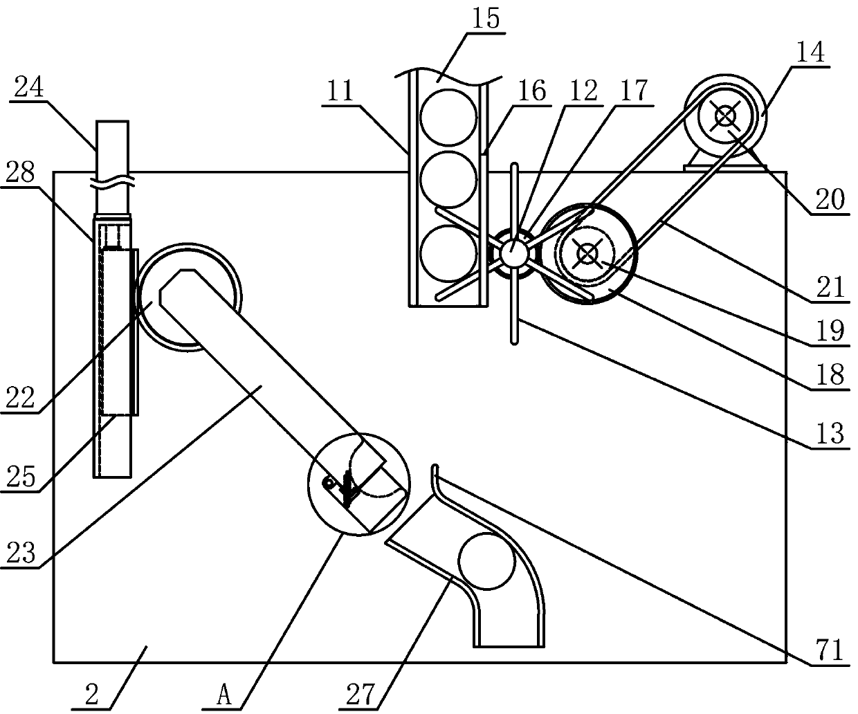
[0022] Such as figure 1 As shown, the present invention is a kind of ball placing mechanism that is used for disc workpiece, comprises disc support 1, bead transmission support 2, bead drop mechanism 3, guide ball mechanism 4, branching mechanism 5, retaining plate guide roller 6, limiter The positioning mechanism 7 and the bearing plate mechanism 8, the bead-passing support 2 is vertically and fixedly arranged on one side above the transmission-disc support 1, and the fixed support rods 9 are vertically fixed and fixed respectively between the two sides below the bead-passing support 2 and the transmission-disc support 1 , the middle par...


PUM


Abstract

The invention discloses a ball placing mechanism for disc workpieces and belongs to the field of workpiece machining mechanical equipment. A ball conveying support is vertically and fixedly arranged on one side above a disc conveying support, a ball guide mechanism is fixedly arranged on the side, with a ball falling mechanism, of the disc conveying support, a branching mechanism is vertically andfixedly arranged on one side below the ball conveying support, a plurality of conveying disc rotating rollers are sequentially and horizontally connected to the disc conveying support in the horizontal direction in a rotating mode, limiting mechanisms are horizontally and symmetrically arranged on the part, on the two sides below the branching mechanism, of the disc conveying support respectively, a disc carrying mechanism is vertically arranged on the part, in the middle of the lower side of the branching mechanism, of the disc conveying support, a transfer disc is vertically connected to the part, on the lower side of a ball guide material pipe, of the ball conveying support in a rotating mode, and a first branch rotating disc and a second branch rotating disc are symmetrically arrangedon the two sides below the transfer disc respectively. The ball placing mechanism is reasonable in structural design and capable of continuously and accurately placing disc workpiece balls of variousdimensions, improving the production machining automation degree of workpieces and meeting machining and using demands.

Description

technical field [0001] The invention belongs to the field of workpiece processing machinery, and in particular relates to a ball placement mechanism for disc workpieces, which is mainly used in the transmission and processing of disc workpieces. Background technique [0002] The mechanical workpiece is a single piece that makes up the machine and its inseparability. It plays an important role in the automation industry. The mechanical workpiece includes the connection of parts, the supporting parts, the lubricating lubrication system and the sealing Components, components of the transmission system that transmits motion and energy, there are many types of workpieces, which can be mainly divided into: shaft sleeve workpieces, disc cover workpieces, fork bracket workpieces and box body workpieces according to the function and shape of the workpiece. The main part of the shaft sleeve workpiece is a coaxial revolving body, which mainly plays the role of supporting rotation and t...

Claims


Application Information

Patent Timeline
IPC IPC(8): B23P19/00
CPCB23P19/001
Inventor 葛巧红
Owner 临沂威尔森新型材料有限公司
Why Eureka
Try Eureka