Mounting workbench for pump part machining

A technology for parts and workbenches, applied in the field of workbenches, can solve the problem of not being able to absorb shock and buffer, and achieve the effect of improving stability and convenient use

Inactive Publication Date: 2020-02-04
湖北鑫敏泵业有限公司
View PDF0 Cites 1 Cited by
  • Summary
  • Abstract
  • Description
  • Claims
  • Application Information

AI Technical Summary

Problems solved by technology

[0003] During the production and processing of pump parts, a workbench is required for installation, but the existing installation workbench has some shortcomings in the process of use. For example, the installation panel is directly fixed on the processing table, which cannot play a role in shock absorption and buffering. Work

Method used


Image

  • Mounting workbench for pump part machining
  • Mounting workbench for pump part machining
  • Mounting workbench for pump part machining

Examples


Embodiment 1

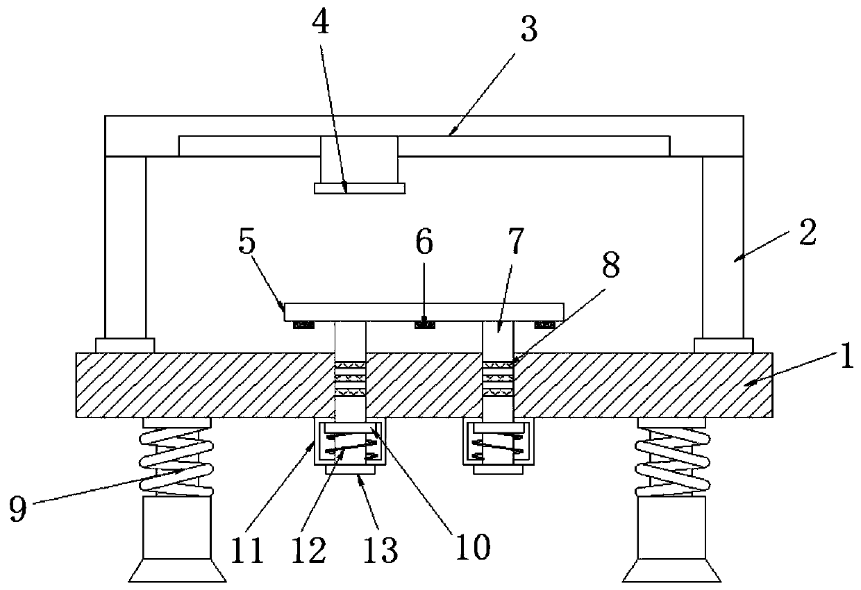
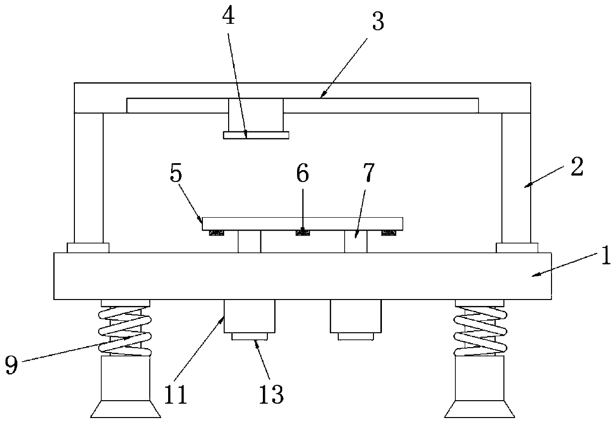
[0023] refer to figure 1 and figure 2 , an installation workbench for pump parts processing, including a base 1, two symmetrically distributed sockets are opened at the center of the outer wall of the top of the base 1, and a movable rod 7 is movably inserted in the socket, and the movable rod 7 There are a pair of equidistant annular grooves on the outer wall of the circumference, and a damping ring 8 is embedded in the annular groove, and the outer wall of the damping ring 8 is attached to the inner wall of the socket, and the same installation panel 5 is fixed on the top of the two movable rods 7. Two limit frames 11 corresponding to the movable rod 7 are fixed on the outer wall of the bottom of the table 1, and the bottom outer wall of the movable rod 7 passes through the limit frame 11 and is fixed with a fixed ring 13, and the outer wall of the movable rod 7 bottom is fixed with a limit ring. 10, and a spring 12 is fixed inside the limiting frame 11, and the spring 12 ...

Embodiment 2

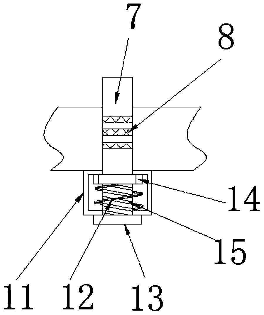
[0027] refer to image 3 , a kind of installation workbench for processing parts and components of a pump. The difference between this embodiment and Embodiment 1 is that there are threads 15 on the outer wall of the circumference of the bottom end of the movable rod 7, and the limit ring 10 is replaced by a collar 14, and the collar 14 The thread is sleeved on the thread 15 of the movable rod 7 .

[0028] The working principle of this embodiment: the collar 14 can compress the spring 12 when rotating on the movable rod 7, so as to realize the adjustment of the initial type variable of the spring 12, and then flexibly adjust the initial damping intensity.


PUM


Abstract

The invention discloses a mounting workbench for pump part machining. The workbench comprises a base table, wherein two plugging ports which are symmetrically distributed are formed in the center of the outer wall of the top of the base table, movable rods are movably inserted into the plugging ports, pairs of annular grooves which are distributed at equal distances are formed in the circumferenceouter walls of the movable rods, damping rings are embedded in the annular grooves, the outer walls of the damping rings are attached to the inner walls of the plugging ports, the top ends of the twomovable rods are fixed with the same one mounting panel, two limiting frames corresponding to the movable rods are fixed to the outer wall of the bottom of the base table, the bottom ends of the movable rods penetrate through the outer walls of the bottoms of the limiting frames to be fixedly provided with fixing rings, limiting rings are fixed to the outer walls of the bottom ends of the movablerods, and springs are fixed in the limiting frames. The workbench performs buffering and supporting effect on the movable rods and the mounting panel, when vibration occurs on the mounting panel, thelimiting rings perform micro-amplitude compression on the springs, the damping rings can buffer the reset work of the springs, and the stability of the mounting panel is integrally improved.

Description

technical field [0001] The invention relates to the technical field of workbenches, in particular to an installation workbench for processing parts of pumps. Background technique [0002] A pump is a machine that moves or pressurizes a fluid. It transfers the mechanical energy of the prime mover or other external energy to the liquid to increase the energy of the liquid. The pump is mainly used to transport liquids such as water, oil, acid and alkali liquid, emulsion, suspoemulsion and liquid metal, and can also transport liquid, gas mixture and liquid containing suspended solids. Pumps can usually be divided into three categories according to their working principles: positive displacement pumps, dynamic pumps and other types of pumps. [0003] During the production and processing of pump parts, a workbench is required for installation, but the existing installation workbench has some shortcomings in the process of use. For example, the installation panel is directly fixe...

Claims


Application Information

Patent Timeline
Patent Type & Authority Applications(China)
IPC IPC(8): B25B27/00B25H1/02F16F15/04
CPCB25B27/00B25H1/02F16F15/04
Inventor 熊少勃
Owner 湖北鑫敏泵业有限公司
Why Eureka
Try Eureka