Rope releasing device for unmanned aerial vehicle

A machine rope releaser and UAV technology, which is applied in the field of fire rescue equipment, can solve the problem that the UAV rope releaser is difficult to arrange the traction rope in high buildings smoothly, and achieve the effect of convenient layout, high efficiency and easy control of the traction rope

Active Publication Date: 2020-02-04
ZHEJIANG TOPSUN LOGISTIC CONTROL CO LTD
View PDF21 Cites 1 Cited by
  • Summary
  • Abstract
  • Description
  • Claims
  • Application Information

AI Technical Summary

Problems solved by technology

[0012] The purpose of the present invention is to solve the above-mentioned problems in the existing technology, and propose a UAV rope release device. The present invention solves the problem that the existing UAV rope release device is difficult to arrange the traction rope of high buildings smoothly and efficiently.

Method used


Image

  • Rope releasing device for unmanned aerial vehicle
  • Rope releasing device for unmanned aerial vehicle
  • Rope releasing device for unmanned aerial vehicle

Examples


Embodiment 1

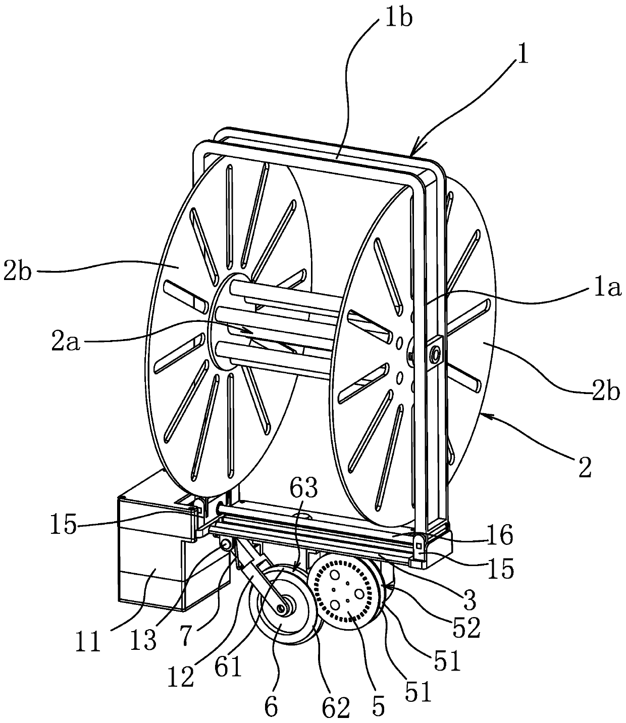
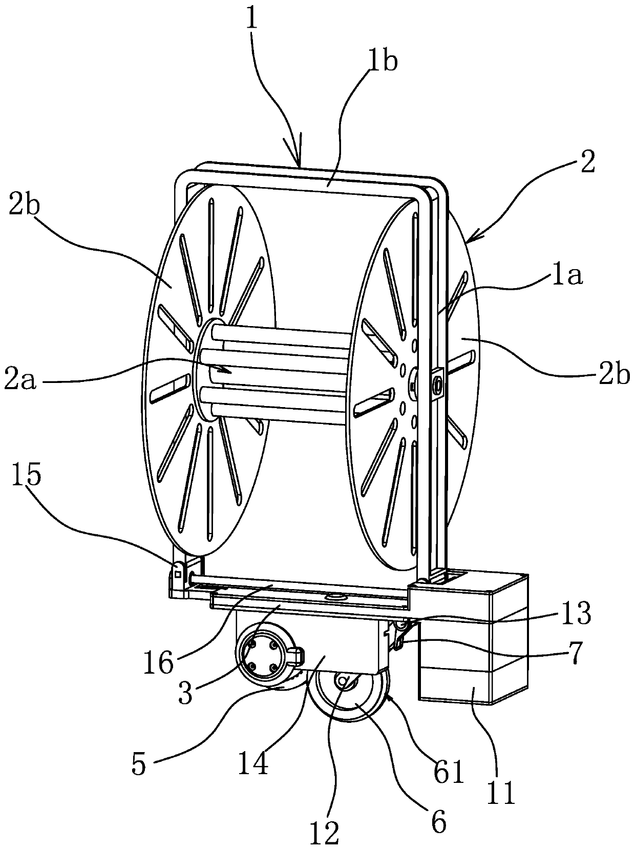
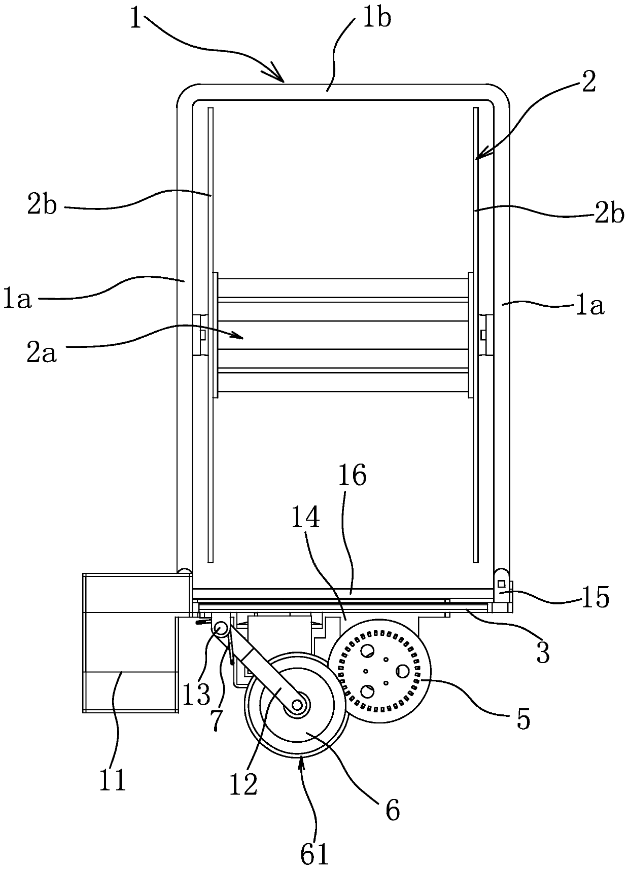
[0047] Such as figure 1 , figure 2 with image 3 As shown, the UAV rope release device includes a rope reel support 1, a throwing frame 3, and a rope reel 2 for winding the traction rope. The rope reel support 1 and the throwing frame 3 are made of aluminum alloy and engineering materials. Composite formation. The throwing frame 3 is strip-shaped, the rope reel support 1 is U-shaped and includes a top beam 1b and two oppositely arranged side support beams 1a, and the rope reel 2 includes a reel 2a, and the two ends of the reel 2a are respectively connected with a 2a is perpendicular to the rope retaining plate 2b, and the two ends of the reel 2a are rotatably connected to two side support beams 1a. The top beam 1b is used to connect with the unmanned aerial vehicle 22, and the throwing frame 3 is connected between the lower ends of the two side support beams 1a. The throwing frame 3 can be separated from the rope reel support 1 by remote control. 3 is provided with a main...

Embodiment 2

[0058] The structure and principle of this embodiment are basically the same as that of Embodiment 1, the difference is that: Figure 16 As shown, the main rotating part is the driving roller 8, the driven part is the driven roller 9, the rope reel 2 has a reel 2a, and the throwing frame 3 is also provided with an installation port 31, and the driving roller 8 and the driven roller 9 are all arranged on The installation openings 31 are all arranged parallel to the reel 2a, and there is a gap between the driving roller 8 and the driven roller 9 for the traction rope to pass through and to clamp the traction rope. When in use, the traction rope passes between the driving roller 8 and the driven roller 9 after being drawn from the rope reel 2 and is clamped by the driving roller 8 and the driven roller 9, so that when the throwing frame 3 falls, the throwing rope Throwing frame 3 just can fall together with traction rope. Moreover, during the take-off process of the UAV, the rot...

Embodiment 3

[0060] The structure and principle of this embodiment are basically the same as that of Embodiment 1. The difference is that the elastic part 7 of Embodiment 1 can use a tension spring, one end of the tension spring is connected to the throwing frame 3, and the other end of the tension spring The end of the connecting wheel frame 12 close to the driven wheel 6 relies on the tension of the extension spring so that the driven wheel 6 has a tendency to always lean against the driving wheel 5 .


PUM


Abstract

The invention provides a rope releasing device for an unmanned aerial vehicle, and belongs to the technical field of fire rescue equipment. The rope releasing device solves the problem that an existing rope releasing device for the unmanned aerial vehicle is difficult to smoothly and efficiently carry out high-rise pulling rope arrangement. The rope releasing device for the unmanned aerial vehiclecomprises a rope disc support used for being connected with the unmanned aerial vehicle, a rope disc used for winding a pulling rope is rotationally arranged on the rope disc support, a detachable throwing frame is further connected to the rope disc support, the throwing support is provided with a main rotating component and a rope releasing driving part used for driving the main rotating component to rotate, and a driven component used for pressing the pulling rope leading out of the rope disc against the main rotating component is rotationally arranged on the throwing frame. According to the rope releasing device for the unmanned aerial vehicle, the arrangement of the pulling rope in the high-rise fire-fighting rescue fire can be efficiently carried out, and the problem that due to thetrouble of the arrangement of the pulling rope and the waste of the time, the best fire-fighting time is missed is avoided.

Description

technical field [0001] The invention belongs to the technical field of firefighting and rescue equipment, and relates to a rope releaser for an unmanned aerial vehicle. Background technique [0002] In recent years, with the acceleration of urbanization across the country, rows of high-rise buildings have become one of the symbols of urban modernization. Due to their large size and dense population, high-rise buildings have many sources of danger and large fire loads. It has brought severe challenges. At present, it is difficult to extinguish a fire in a high-rise building quickly, and it has always been a difficult problem for people to overcome. On the one hand, although the invention of the aerial ladder can send the fire water gun to a high place for fire extinguishing, the use of the aerial ladder is limited by the space, and it is difficult to use the aerial ladder to extinguish the fire in some communities where the road is not wide; The usual height of the existing ...

Claims


Application Information

Patent Timeline
Patent Type & Authority Applications(China)
IPC IPC(8): B65H49/30
CPCB65H49/30
Inventor 阮卜琴牛胜良
Owner ZHEJIANG TOPSUN LOGISTIC CONTROL CO LTD
Why Eureka
Try Eureka