Ejection type infrared suppressor with double layer cooling mixed tubes

An infrared suppression, mixing tube technology for machines/engines, jet propulsion, etc., that solves problems of complexity, shape and size constraints

Inactive Publication Date: 2020-02-04
NANJING UNIV OF AERONAUTICS & ASTRONAUTICS
View PDF6 Cites 7 Cited by
  • Summary
  • Abstract
  • Description
  • Claims
  • Application Information

AI Technical Summary

Problems solved by technology

The second-generation infrared suppressor can greatly reduce the temperature of the exhaust exhaust flame and shield the hot-end components, but compared with the fuselage, the exposed outer mixing tube and exhaust flame are still high-temperature hot spots, because the second-generation infrared The suppressor is only an additional component at the rear of the engine system, and is greatly limited in shape and size. In this context, the third-generation infrared suppressor with the integrated design of the infrared suppressor and the fuselage was developed.
The lobe nozzle-inner mixing tube is the core component of the integrated infrared suppressor. At present, our understanding of its complex aerodynamic mixing performance and infrared stealth effect is almost blank

Method used


Image

  • Ejection type infrared suppressor with double layer cooling mixed tubes
  • Ejection type infrared suppressor with double layer cooling mixed tubes
  • Ejection type infrared suppressor with double layer cooling mixed tubes

Examples


Embodiment Construction

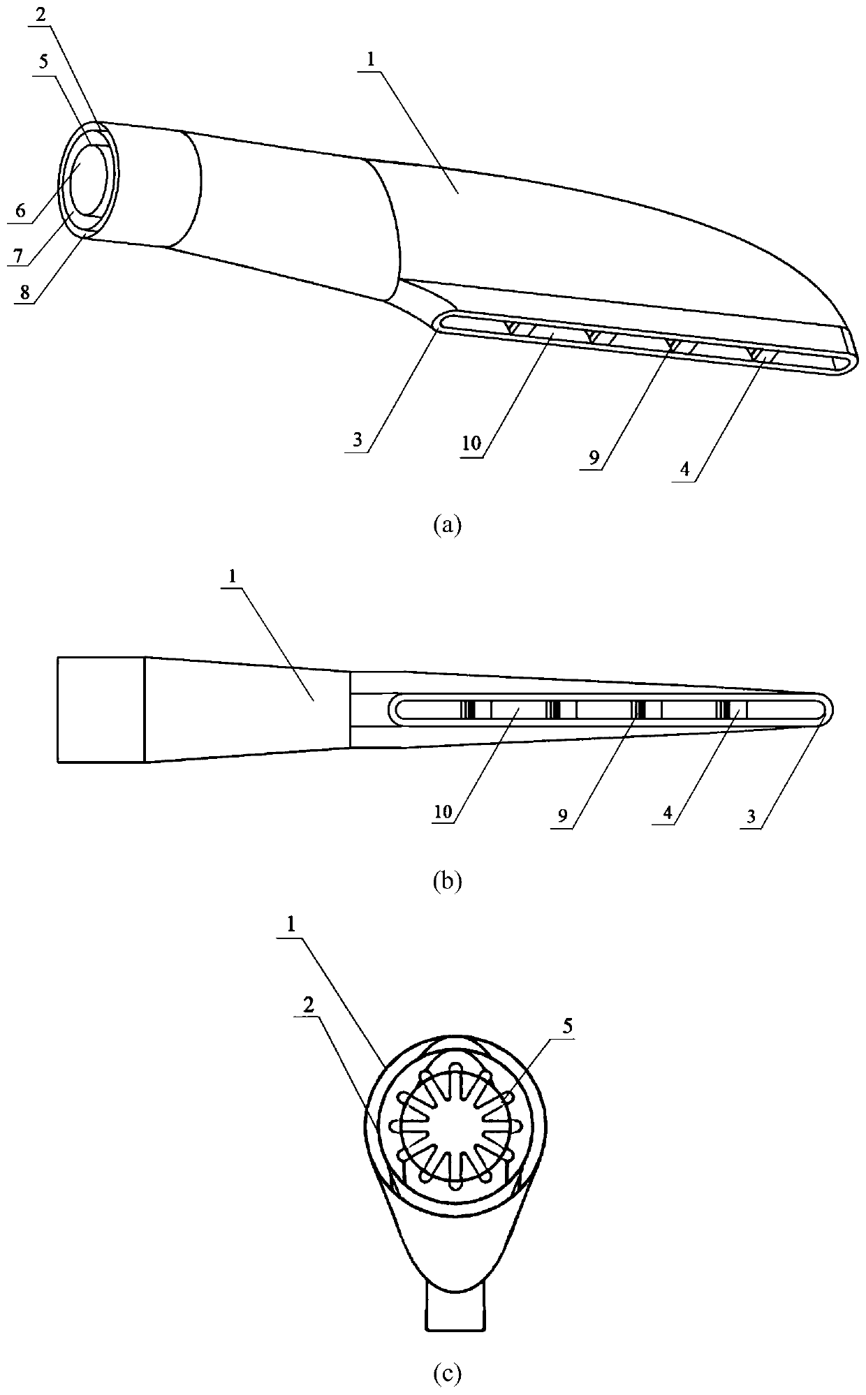
[0027] The present invention provides a double-layer cooling mixing tube ejection infrared suppressor. In order to make the purpose, technical scheme and effect of the present invention clearer, the present invention will be described below in conjunction with the accompanying drawings in the embodiments of the present invention. A more detailed description. It should be pointed out that the specific embodiments described here are only used to explain the present invention, not to limit the present invention.

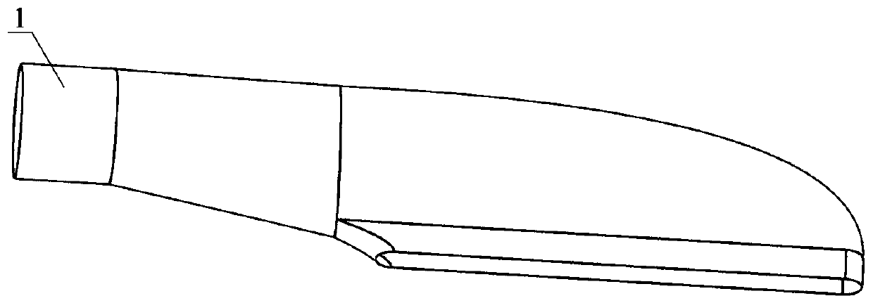
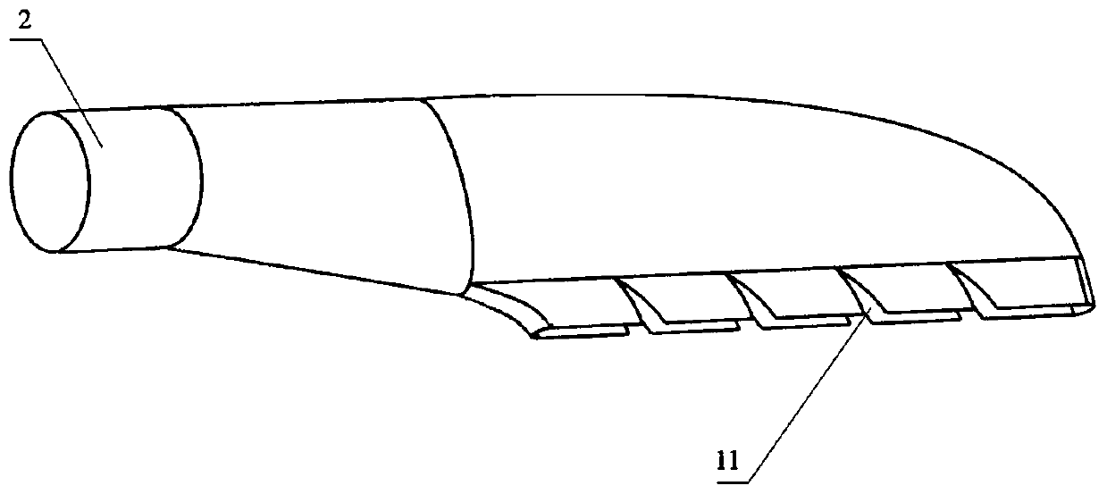
[0028] refer to Figure 1 to Figure 7 As shown, a double-layer cooling mixing tube ejector infrared suppressor of the present invention includes an outer layer mixing tube 1, an inner layer mixing tube 2, a closed ring 3, a hollow deflector 4 with a slit and a lobe nozzle 5. The lobe nozzle 5 is installed in the inner mixing tube 2, including a straight pipe section and an asymmetrical lobe. The asymmetrical lobe has a longer lobe on the side near the outer ridge line...


PUM


Abstract

The invention provides an ejection type infrared suppressor with double layer cooling mixed tubes. The infrared suppressor comprises the inner and outer double layer mixed tubes, a lobe nozzle and a hollow flow director with a slit. According to the infrared suppressor, the upper and lower asymmetric lobe nozzle is adopted, so that the high-temperature exhaust gas at each part can just attach thewall at outlets of the mixed tubes, the high-temperature exhaust momentum is utilized to the maximum extent, and the outside cold air is guided as much as possible; forced cooling air flow is introduced into a forced air inlet of the double-layer mixed tube, the forced cooling airflow flows through an interlayer between the double layer mixed tubes, and the wall surfaces of the mixed tubes are cooled; the forced cooling airflow flows into the inner layer mixed tube through the slit of a hollow diversion guide plate and is blended with the hot exhaust gas, so that the exhaust temperature is further reduced; the hot exhaust gas in the double layer mixed tubes generates multiple streams through the hollow diversion guide plate, and the mixing uniformity of the high-temperature exhaust gas andthe injection cooling airflow is improved; and the temperature and the exhaust temperature of the wall surfaces of the mixed tubes can be greatly reduced by adopting the injection type infrared suppressor with the double layer cooling mixed tubes, and the infrared radiation intensity is reduced.

Description

technical field [0001] The invention relates to a double-layer cooling mixing tube ejection infrared suppressor, which belongs to the technical field of aero-engine exhaust system design and infrared suppression. Background technique [0002] Due to its good maneuverability, armed helicopters can not only carry out precise strikes on ground and ultra-low-altitude targets, but also be used to perform important military tasks such as emergency transportation, air command, and early warning in the air. It has become an important conventional weapon in modern warfare. However, with the rapid development of infrared imaging detection systems, airborne infrared forward-looking devices and new infrared guided weapons, the sensitivity of infrared detection equipment and the recognition ability of the system have been significantly improved, and the strike level of infrared guided weapons has been greatly improved. Gunships with powered propulsion systems are increasingly threatened ...

Claims


Application Information

Patent Timeline
Patent Type & Authority Applications(China)
IPC IPC(8): F02K1/82
CPCF02K1/822F02K1/825
Inventor 张靖周郑禛单勇蒋坤宏
Owner NANJING UNIV OF AERONAUTICS & ASTRONAUTICS
Why Eureka
Try Eureka