
Optical fiber cable long-distance detection auxiliary rod and use method

A long-distance, auxiliary rod technology, applied in the field of instrument measurement of spectral information and image information, can solve problems such as not being suitable for observers to observe at close range, unable to obtain target image information, and view target object spectral information, so as to save manpower Material resources, improved simplicity, and accurate data acquisition

Pending Publication Date: 2020-02-04
DALIAN OCEAN UNIV
View PDF0 Cites 0 Cited by
  • Summary
  • Abstract
  • Description
  • Claims
  • Application Information

AI Technical Summary

Problems solved by technology

[0003] The current detection equipment generally uses auxiliary instruments such as tripods and pistol handles to obtain data from different directions and positions of the target when measuring the spectral information of outdoor objects. , Swamp) is not suitable for observers to observe at close range, and the traditional detection method cannot obtain the image information of the target object, and the staff need to hold the optical fiber probe to aim at the target object when detecting, at this time, the detection personnel cannot stably operate the computer by one person to view Spectral information of the target object, unable to operate the computer and fiber optic probe at the same time

Method used


Image

  • Optical fiber cable long-distance detection auxiliary rod and use method
  • Optical fiber cable long-distance detection auxiliary rod and use method
  • Optical fiber cable long-distance detection auxiliary rod and use method

Examples


Embodiment Construction

[0040] The following will clearly and completely describe the technical solutions in the embodiments of the present invention with reference to the accompanying drawings in the embodiments of the present invention. Obviously, the described embodiments are only some, not all, embodiments of the present invention. Based on the embodiments of the present invention, all other embodiments obtained by persons of ordinary skill in the art without creative efforts fall within the protection scope of the present invention.

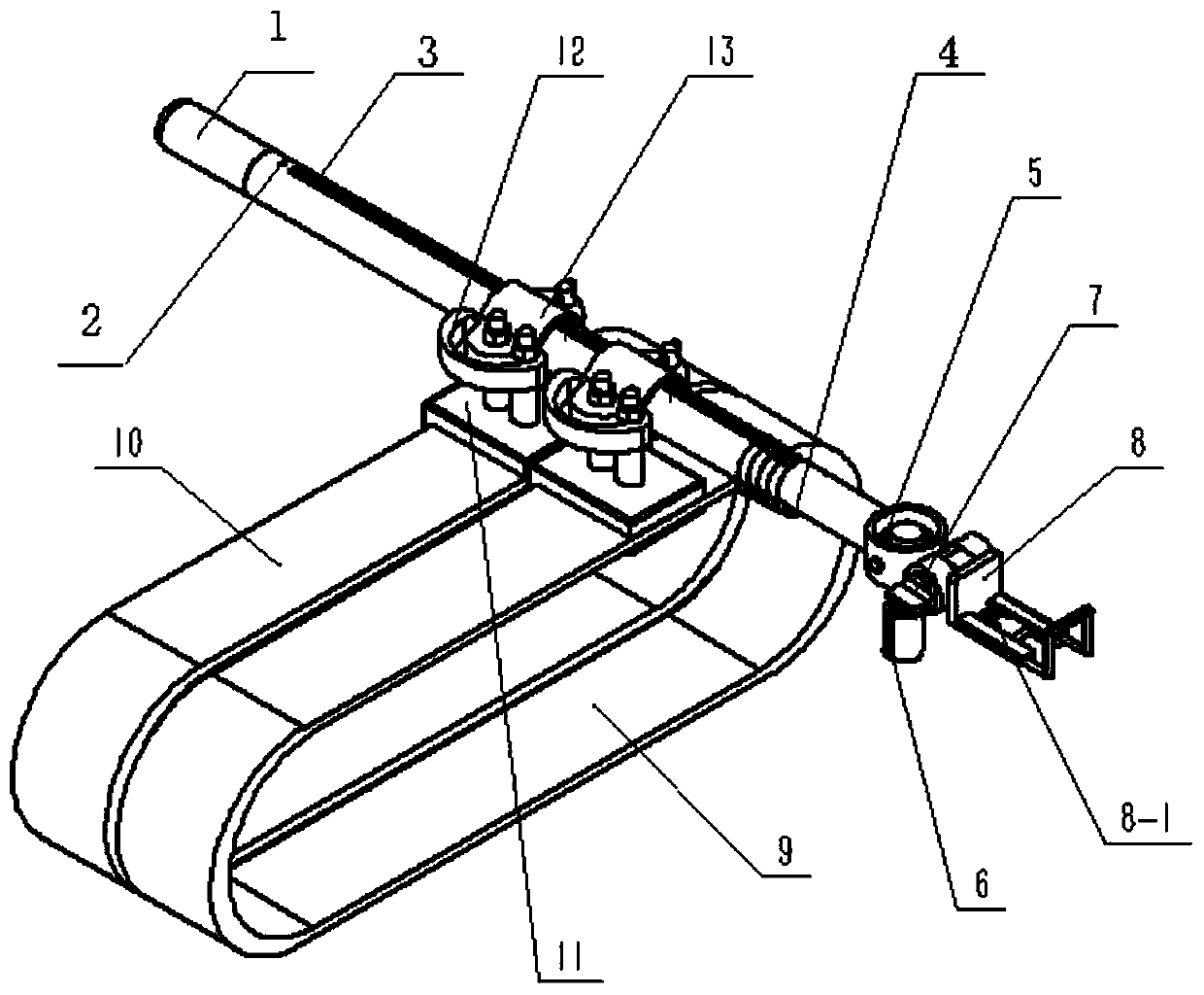
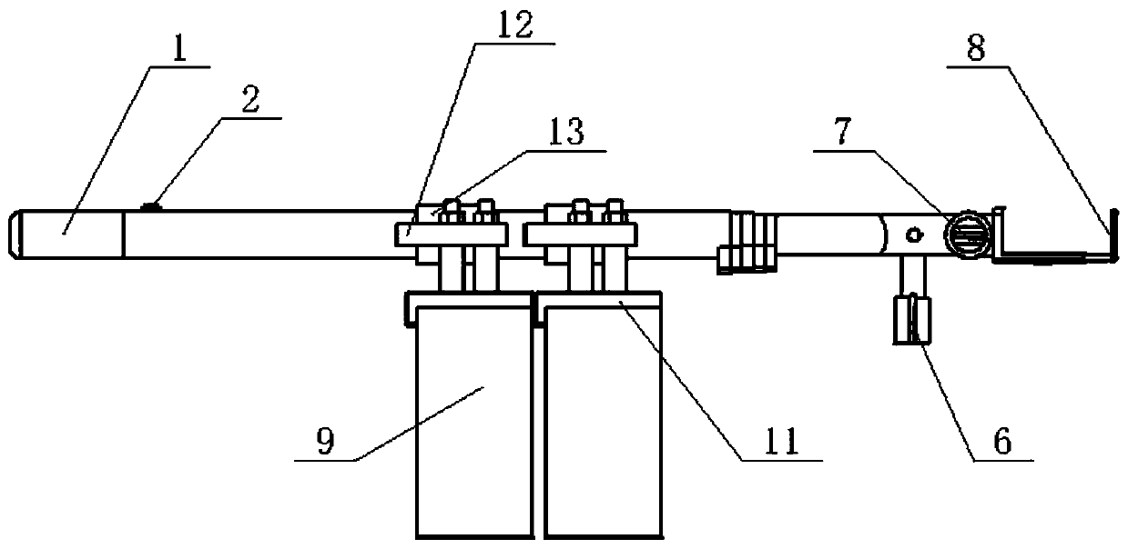
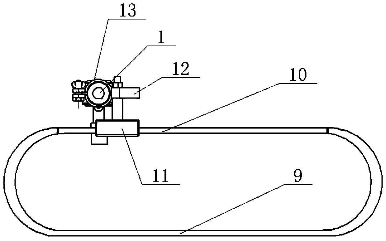
[0041] see Figure 1-10 , the present invention provides a technical solution: an optical fiber cable long-distance detection auxiliary rod and its use method, including a telescopic main rod 1, a camera button 2, a detection component, a camera fixing mechanism, a rod connector 13 and a waist fixing component, The telescopic main rod 1 is an electric telescopic rod or a manually adjustable telescopic rod, the camera button 2 is arranged on the upper surface of the...


PUM


Abstract

The invention provides an optical fiber cable long-distance detection auxiliary rod and a using method. The optical fiber cable long-distance detection auxiliary rod comprises a telescopic main rod, acamera button, a detection assembly, a camera fixing mechanism, a connector with a rod as well as a waist fixing assembly, the camera button is arranged on the upper surface of a handle end of the telescopic main rod, the input end of the camera button is electrically connected with the output end of an external power supply, the detection assembly is arranged on the side surface of the telescopic end of the telescopic main rod, the camera fixing mechanism is installed on the side surface of the detection assembly, the connector with the rod is sleeved on the outer side surface of the telescopic main rod, and a main rod angle adjuster is fixedly installed on the outer side of the connector with the rod. According to the optical fiber cable long-distance detection auxiliary rod and the using method, the length of the auxiliary rod can be adjusted through stretching and retracting of the telescopic main rod, the purpose that an observer can easily acquire spectral information of a target object in the detection area which is difficult to reach is achieved, and the camera can be fixed through the camera fixing mechanism so as to capture and obtain the image information of the targetobject in the detection area.

Description

technical field [0001] The invention relates to the technical field of instrument measurement of spectral information and image information, in particular to an optical fiber cable long-distance detection auxiliary rod and a use method thereof. Background technique [0002] Surface object spectrometer is an instrument used to measure radiant energy (radiance and irradiance). It can be used to measure the reflectivity, transmittance, radiance or irradiance of targets in many fields. It can use optical fiber cables and cooperate with pistol handles. , for indoor and outdoor target radiation collection, that is, the fiber optic cable is aimed at the target object, and the spectrum is collected with the help of the ambient light source, which is suitable for a variety of lenses. [0003] The current detection equipment generally uses auxiliary instruments such as tripods and pistol handles to obtain data from different directions and positions of the target when measuring the sp...

Claims


Application Information

Patent Timeline
Patent Type & Authority Applications(China)
IPC IPC(8): F16M13/04F16M11/04F16M11/06G01J3/02
CPCF16M11/043F16M11/06F16M13/04G01J3/0202G01J3/0218
Inventor 李微龚潇漆林王文硕刘旭龙孙悦
Owner DALIAN OCEAN UNIV
Learn More