
Large-magnification continuous zooming area array scanning infrared optical system and image motion compensation method

An infrared optical system and optical system technology, applied in optics, optical components, radio wave measurement systems, etc., can solve the problems that the continuous tracking of the small field of view cannot be taken into account, and the target resolution cannot be continuously changed, so as to achieve wide working Effect of temperature range

Active Publication Date: 2020-02-04
SHANGHAI INST OF TECHNICAL PHYSICS - CHINESE ACAD OF SCI
View PDF11 Cites 7 Cited by
  • Summary
  • Abstract
  • Description
  • Claims
  • Application Information

AI Technical Summary

Problems solved by technology

During its 360° scan search and staring tracking, the resolution of the target cannot be continuously changed, and it cannot take into account the functions of large field of view search and small field of view continuous tracking

Method used


Image

  • Large-magnification continuous zooming area array scanning infrared optical system and image motion compensation method
  • Large-magnification continuous zooming area array scanning infrared optical system and image motion compensation method
  • Large-magnification continuous zooming area array scanning infrared optical system and image motion compensation method

Examples


Embodiment Construction

[0050] Now in conjunction with embodiment, accompanying drawing, the present invention will be further described:

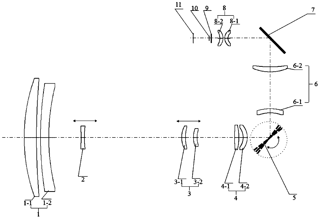
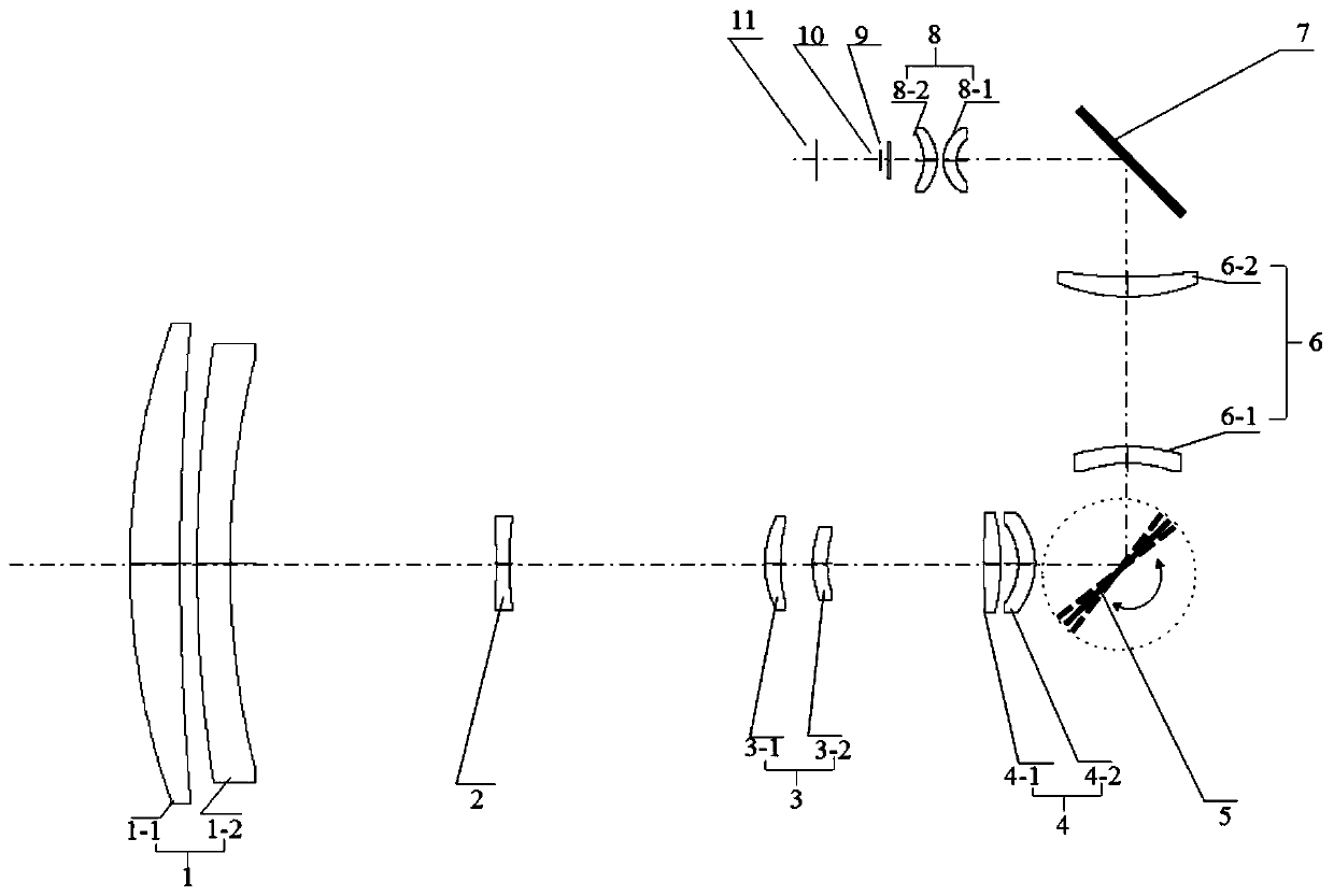
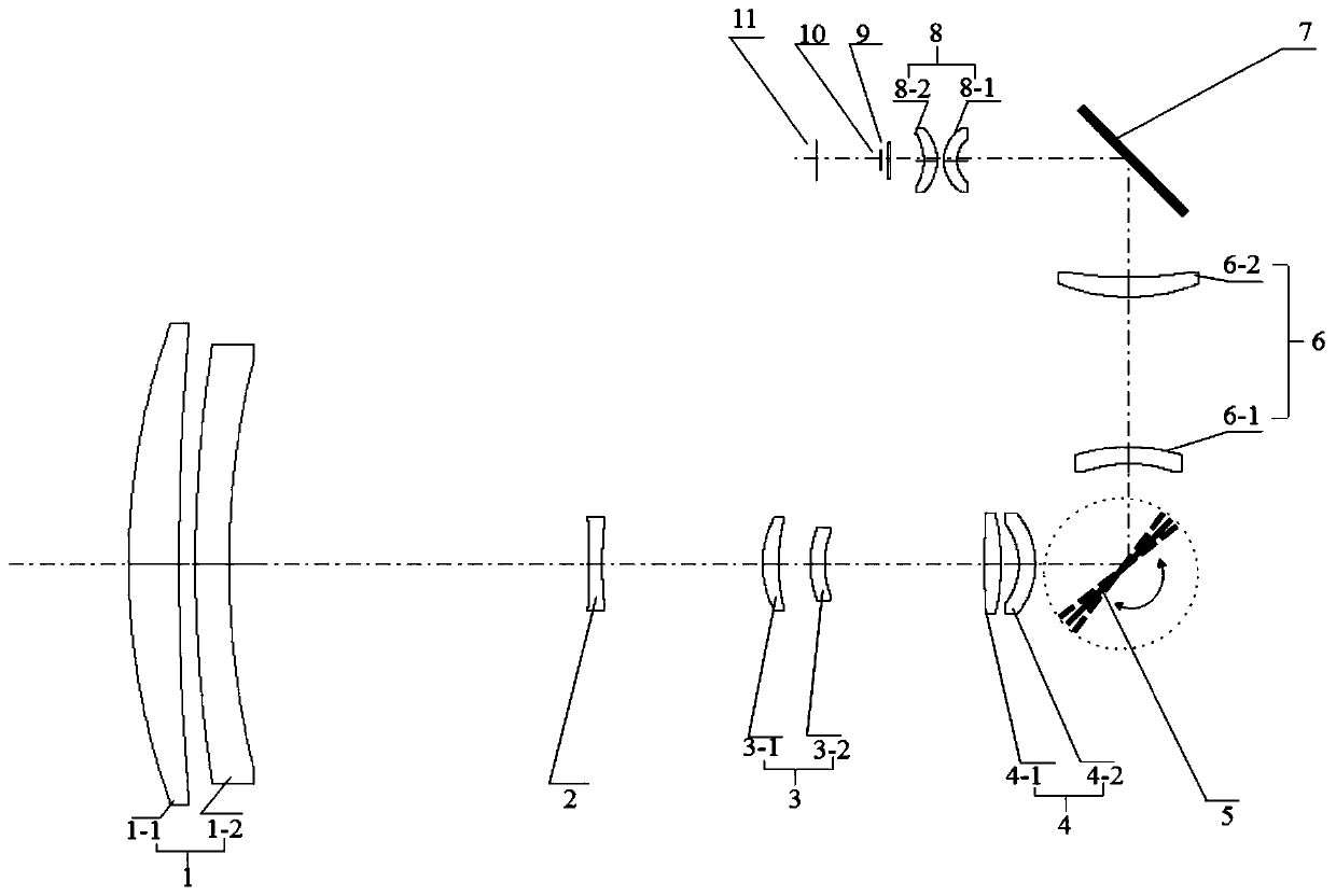
[0051] According to attached figure 1 , figure 2 , image 3 ,, Figure 4 , Figure 5 , Image 6 , Figure 7 As shown, the large-magnification continuous zoom area scanning infrared optical system of the present invention sequentially includes a front fixed group 1, a variable magnification group 2, a compensation group 3, a rear fixed group 4, a scanning galvanometer 5, and a secondary meeting from the object side to the image side. Gathering group 6 , turning mirror 7 , tertiary imaging group 8 , optical window 9 , and aperture stop 10 .

[0052] In the following, a high-magnification continuous zoom area scan infrared optical system with a focal length range of 28 mm to 560 mm is taken as an example for description. The optical system of the present invention is a 20 times large magnification continuous zoom area scanning optical system with a working b...


PUM


Abstract

The invention discloses a large-magnification continuous zooming area array scanning infrared optical system and an image motion compensation method. The large-magnification continuous zooming area array scanning infrared optical system sequentially comprises, front an object surface to an image surface: a front fixed group, a variable magnification group, a compensation group, a back fixed group,a scanning galvanometer, a secondary convergence group, a turning reflector, a tertiary imaging group, an optical window and an aperture diaphragm. The maximum zooming magnification can reach 20 times, and the distortion at each focal length is less than 1%; when the scanning galvanometer is in a locked state, the optical system can work in a gaze tracking mode; and when the scanning galvanometeris in a backward scanning mode, the optical system is in a peripheral scanning search mode, the movement of the object surface within an exposure time caused by the rotation of a scanning platform can be compensated by the backward scanning of the scanning galvanometer, and clear and stable imaging during rotary scanning is kept. The system adopts the form of positive group compensation mechanical zooming and middle parallel optical path scanning to achieve multi-range area array scanning and large-magnification continuous zooming gaze tracking. The large-magnification continuous zooming areaarray scanning infrared optical system can be practically used in an infrared system integrating search with tracking and based on an area array detector.

Description

technical field [0001] The invention relates to an infrared detection optical system, in particular to a large-magnification continuous zoom area scanning infrared optical system. Background technique [0002] The infrared search and track system has two functions of target search and target tracking. It has many advantages such as good concealment, wide detection range, high positioning accuracy, strong ability to identify camouflage, and anti-electromagnetic interference. It has been widely concerned and applied. [0003] The working mode of the infrared search and tracking system is as follows: First, the infrared system platform scans and images in a 360° azimuth or within the angular range of key areas at a certain speed. After finding the target, the system switches to tracking mode. This requires the infrared search and tracking system to have the functions of continuous scanning imaging and staring imaging. With the application requirements of the integration of se...

Claims


Application Information

Patent Timeline
Patent Type & Authority Applications(China)
IPC IPC(8): G02B15/167G02B26/10G02B27/00G01S7/481G01S17/06G01S17/66
CPCG02B15/167G02B26/105G02B27/0031G01S7/4817G01S17/06G01S17/66Y02A90/10
Inventor 丁学专黄姜卿李范鸣刘士建孙夏杰于洋
Owner SHANGHAI INST OF TECHNICAL PHYSICS - CHINESE ACAD OF SCI
Learn More