Eureka AIR delivers breakthrough ideas for toughest innovation challenges, trusted by R&D personnel around the world.

Pantograph-catenary contact force optimization design method

A technology for optimizing design and contact force, applied in design optimization/simulation, geometric CAD, overhead lines, etc., can solve problems such as structural fatigue and damage, achieve the effects of reducing stress, improving reliability, and reducing contact force fluctuations

Inactive Publication Date: 2020-02-04
NANJING UNIV OF AERONAUTICS & ASTRONAUTICS
View PDF1 Cites 0 Cited by
  • Summary
  • Abstract
  • Description
  • Claims
  • Application Information

AI Technical Summary

Problems solved by technology

However, the goal of active control in the existing literature is mainly to maintain an appropriate contact force, while ignoring disturbances from the outside world, such as disturbances from locomotives, parametric disturbances from catenary, noise from sensors, etc.
This makes the traditional design only maintain the proper contact force, but may cause structural fatigue and even serious damage at the connection between the pantograph and the locomotive

Method used


Image

  • Pantograph-catenary contact force optimization design method
  • Pantograph-catenary contact force optimization design method
  • Pantograph-catenary contact force optimization design method

Examples


Embodiment Construction

[0027] The present invention will be further explained below in conjunction with the accompanying drawings.

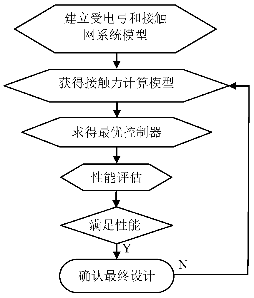
[0028] Such as figure 2 As shown, a pantograph-catenary contact force optimization design method includes the following steps:

[0029] Step 1: Establish pantograph and catenary system models;

[0030] Step 2: Obtain the contact force calculation model;

[0031] Step 3: According to the spectral characteristics, use the Navellinna-Pick interpolation method to obtain the transfer function that meets the optimal value, so as to obtain the optimal controller;

[0032] Step 4: Perform performance evaluation. If the performance index requirements are met, then confirm the optimal design; otherwise, return to step 1, and iterate the optimal performance of the optimal controller by checking the exact values ​​of each known parameter.

[0033] In this embodiment, step 1 adopts the following scheme:

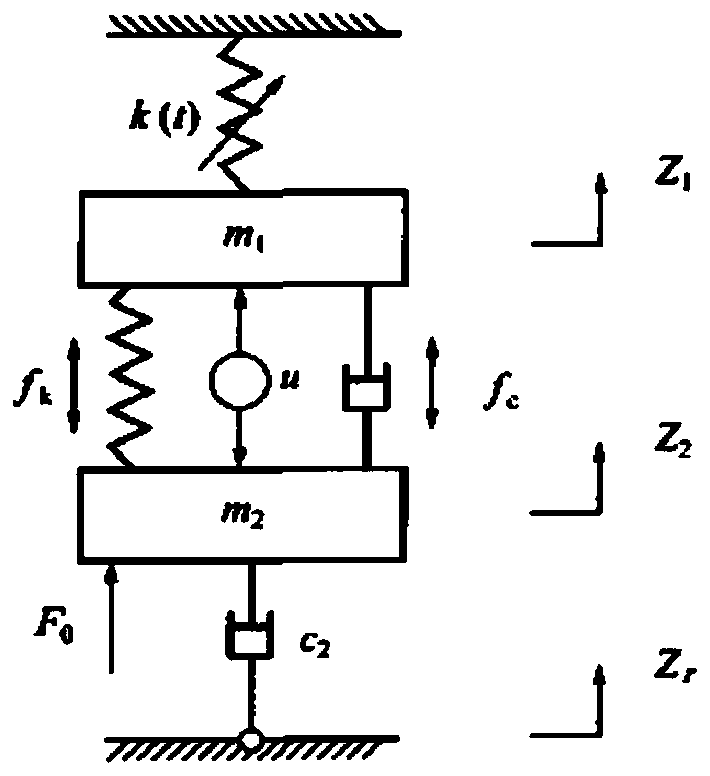
[0034] use as figure 1 A simplified diagram of the pantograph and caten...


PUM


Abstract

The invention discloses a pantograph-catenary contact force optimization design method. The method comprises the following steps: establishing a pantograph and catenary system model; obtaining a contact force calculation model; according to the spectral characteristics, adopting a Navellinna-Pick interpolation method to obtain a transfer function conforming to the optimal value, and therefore obtaining an optimal controller; performance evaluation is carried out, and if performance index requirements are met, the optimal design is confirmed; otherwise, the optimal performance of the optimal controller is iterated by checking the accurate value of each known parameter. According to the invention, the optimized pantograph-catenary system can reduce the stress of the pantograph and the locomotive, reduce the probability of structural fatigue damage and improve the reliability of the whole pantograph-catenary system while reducing the fluctuation of the contact force.

Description

technical field [0001] The invention belongs to the field of pantograph-catenary systems, and in particular relates to an optimal design method of pantograph-network contact force. Background technique [0002] A high-performance EMU must have a stable and reliable power supply, and the only way for the train to obtain electric energy is through the pantograph on the roof, which introduces the high-voltage alternating current on the catenary into the train. However, for trains running on high-speed railways, because the trains are very fast, the trains will become more unstable and unreliable by taking power through the pantograph. It is a key technical problem to solve the pantograph-catenary relationship between the pantograph and the catenary. [0003] Two solutions that are widely concerned at present are: 1) adopting more advanced electrical skateboard materials; 2) adopting active control technology. When the speed of the train is 400 kilometers per hour, the relativ...

Claims


Application Information

Patent Timeline
Patent Type & Authority Applications(China)
IPC IPC(8): G06F30/15G06F30/20B60M1/12
CPCB60M1/12
Inventor 王继强
Owner NANJING UNIV OF AERONAUTICS & ASTRONAUTICS
Why Eureka
Eureka Blog
Learn More