
Integrated adjustable bridge structure for high-voltage cable construction

A high-voltage cable and bridge structure technology, applied in electrical components and other directions, can solve the problems of inability to change the width of the bridge, high construction cost, complicated construction, etc., and achieves good fixing effect, convenient storage and transportation, and improves the effect of construction speed.

Active Publication Date: 2020-02-04
JIANGSU ELECTRIC POWER CO
View PDF14 Cites 4 Cited by
  • Summary
  • Abstract
  • Description
  • Claims
  • Application Information

AI Technical Summary

Problems solved by technology

[0005] In order to solve the above technical problems, the present invention provides an integrated adjustable bridge structure for high-voltage cable construction to solve the problem that the existing integrated bridge cannot change the width of the bridge due to its fixed structure, and different widths need to be selected according to actual use requirements during use. Type of bridge, but also to reserve a certain amount of reserve, in the later maintenance and use process, when the spare amount is insufficient, it is necessary to increase the bridge or replace the bridge of different width models, the construction is complicated, the construction period is long, and the construction cost is high question

Method used


Image

  • Integrated adjustable bridge structure for high-voltage cable construction
  • Integrated adjustable bridge structure for high-voltage cable construction
  • Integrated adjustable bridge structure for high-voltage cable construction

Examples


Embodiment

[0032] As attached figure 1 Attached Figure 8 Shown:

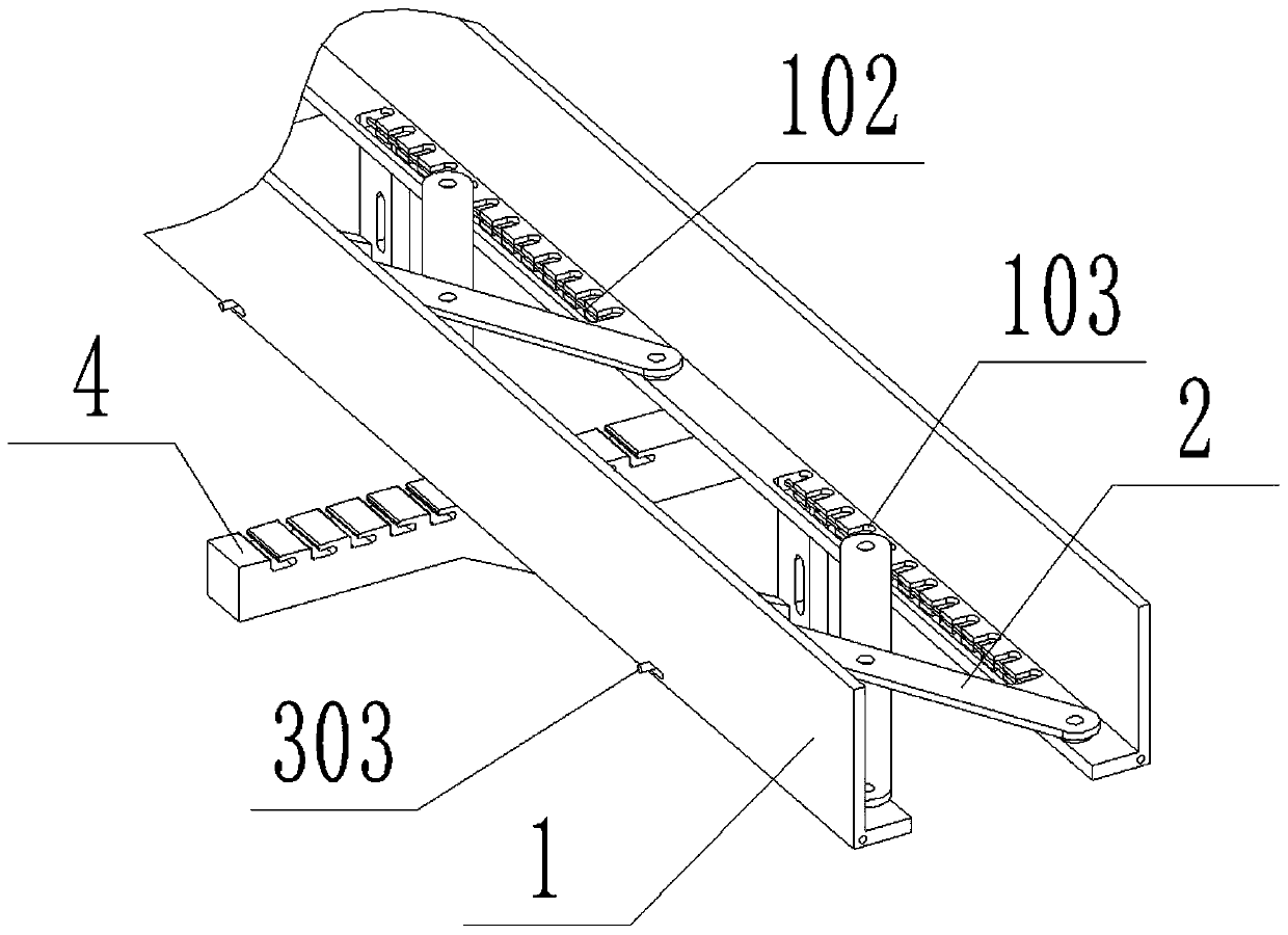
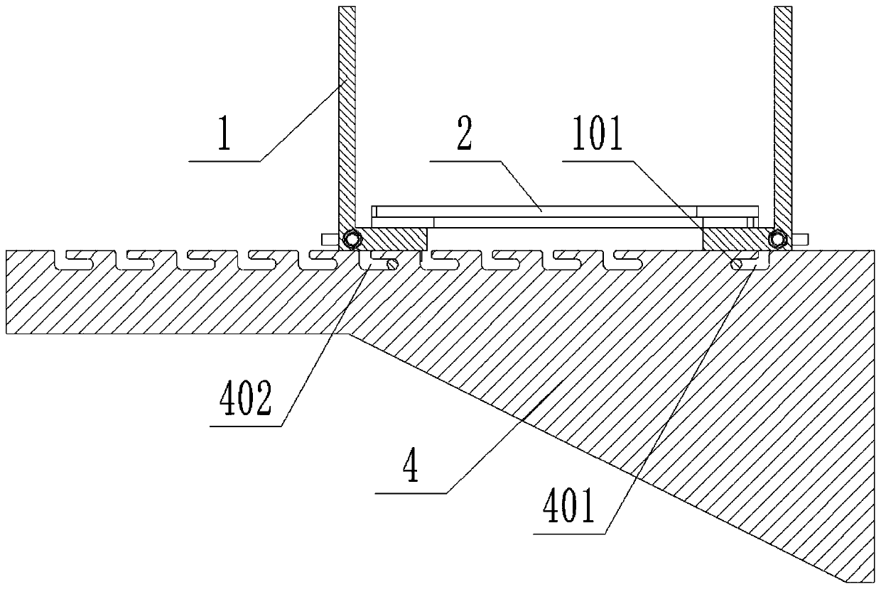
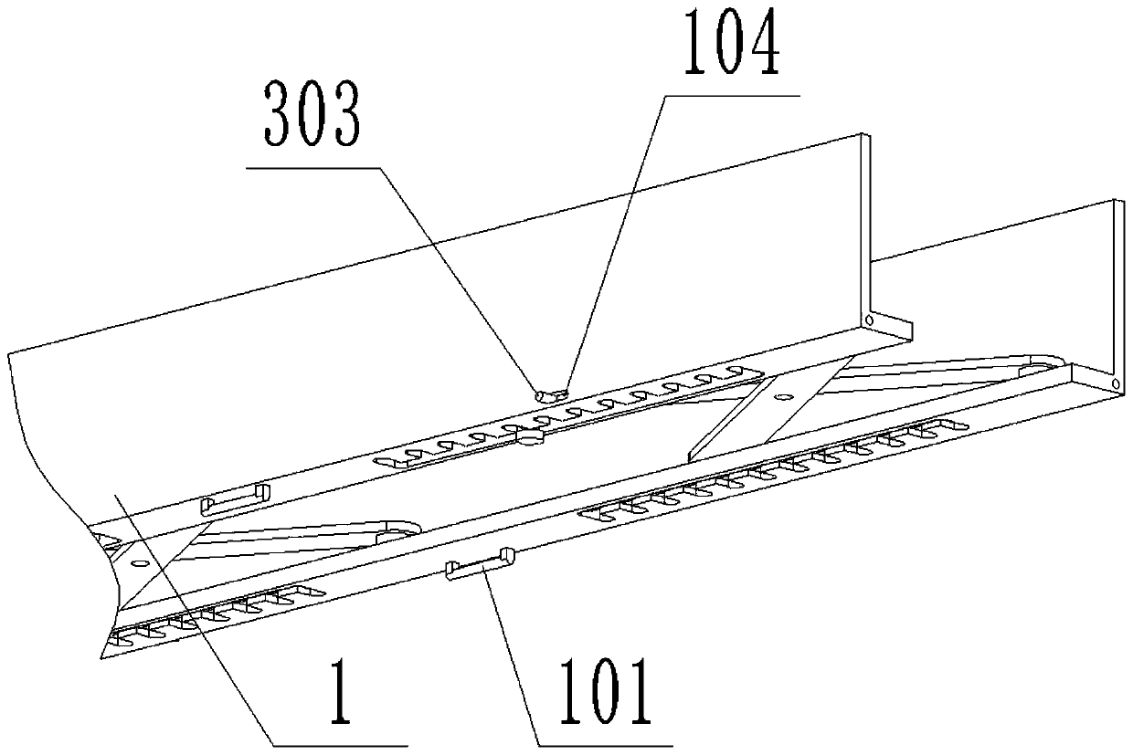
[0033] The present invention provides an integrated adjustable bridge structure for high-voltage cable construction, including: side plate 1, fixed clamping shaft 101, sliding groove 102, clamping groove 103, lock groove 104, bottom connecting rod 2, roller 201, lock pin 3. Spring 301, tooth 302, hand dial 303, bridge support arm 4, fixed end slot 401 and movable end slot 402; the bottoms of the two sets of side plates 1 are connected by multiple sets of bottom connecting rods 2; each set of side plates 1 A set of lock pins 3 are slidably connected to the inner side of the bottom; multiple sets of bridge support arms 4 are inserted together at the bottom of the two sets of side plates 1.

[0034] Among them, the bottom surface of the side plate 1 is provided with multiple sets of sliding grooves 102, and one end of the bottom surface of the bottom connecting rod 2 is axially connected to a set of rollers 201, and the rollers ...


PUM


Abstract

The invention provides an integrated adjustable bridge structure for high-voltage cable construction. The integrated adjustable bridge structure comprises side plates, a fixed clamping shaft and a movable end clamping groove; the bottoms of two groups of the side plates are connected through multiple groups of bottom surface connecting rods; a group of lock pins are slidably connected to the innersides of the bottoms of each group of side plates; and multiple groups of bridge support arms are plugged together at the bottoms of the two groups of the side plates. According to the integrated adjustable bridge structure for the high-voltage cable construction provided by the invention, the two groups of the side plates are connected together and a bottom surface is formed by adopting a shears-fork mechanism; the distance between the two groups of side plates can be arbitrarily adjusted during use, and the bridge width can be conveniently adjusted; at the same time, a roller is fixed on the clamping groove by a clamping tooth when the clamping tooth is released by hands, so that the shears-fork mechanism cannot be changed, so that the bridge width can be fixed, and different numbers ofcables can be applied; and when cables in the bridge are increased, the width of the bridge can be adjusted without re-adding or replacing the bridge, thereby reducing the installation operations, increasing the construction speed and reducing the cost.

Description

Technical field [0001] The invention belongs to the technical field of electric power engineering, and more specifically, relates to an integrated adjustable bridge structure used for high-voltage cable construction. Background technique [0002] In the process of high-voltage cable construction, bridges are often used to place and protect cables. Integrated bridges are widely used due to their simple structure and fast installation speed. The existing integrated bridges are generally fixed U-shaped structures. [0003] For example, application number: CN201110419890.6. The present invention discloses an integral ladder type cable tray, which includes two ladder sides and a cross arm. The ladder sides and the cross arm are made of a single piece of sheet metal stamping, and the cross arm is provided with A groove-shaped reinforcing rib, both ends of the groove-shaped reinforcing rib are bifurcated in a Y shape, a cross section of the middle part of the groove-shaped reinforcing rib...

Claims


Application Information

Patent Timeline
IPC IPC(8): H02G3/04
CPCH02G3/0437H02G3/0456
Inventor 蒋益龙
Owner JIANGSU ELECTRIC POWER CO
Learn More