An engine cylinder head turning device

A technology of engine cylinder head and flipping device, which is applied in the direction of manufacturing tools and workbenches, etc. It can solve the problems of engine cylinder head damage, fast rotation of the clamping rod, excessive movement of the clamping rod, etc., so as to facilitate processing and repair and avoid clamping Insufficient holding force and accurate clamping force

Active Publication Date: 2021-05-25
WUHU DINGHENG MATERIAL TECH
View PDF10 Cites 1 Cited by
  • Summary
  • Abstract
  • Description
  • Claims
  • Application Information

AI Technical Summary

Problems solved by technology

[0003] At present, the clamping of the engine cylinder head is carried out by moving the clamping rod, but the movement length of the clamping rod is not accurately controlled, which may easily cause inaccurate movement of the clamping rod, and the engine cylinder head cannot be clamped or clamped. Too much movement of the holding rod, too tight clamping of the engine cylinder head will cause damage to the engine cylinder head. At the same time, when the engine cylinder head is turned over, the motor rotation friction is used to drive the clamping rod to rotate. This method cannot control the rotation force of the engine cylinder head , it is easy to cause the clamping rod to rotate quickly due to the self-weight of the engine cylinder head, or the rotation cannot be achieved by turning, and there is no way to carry out the smooth rotation of the engine cylinder head

Method used


Image

  • An engine cylinder head turning device
  • An engine cylinder head turning device
  • An engine cylinder head turning device

Examples


Embodiment Construction

[0020] In order to enable those skilled in the art to better understand the technical solutions of the present invention, the present invention will be described more clearly and completely below in conjunction with the accompanying drawings in the embodiments. Of course, the described embodiments are only a part of the present invention. Not all, based on this embodiment, other embodiments obtained by those skilled in the art without creative efforts are all within the protection scope of the present invention.

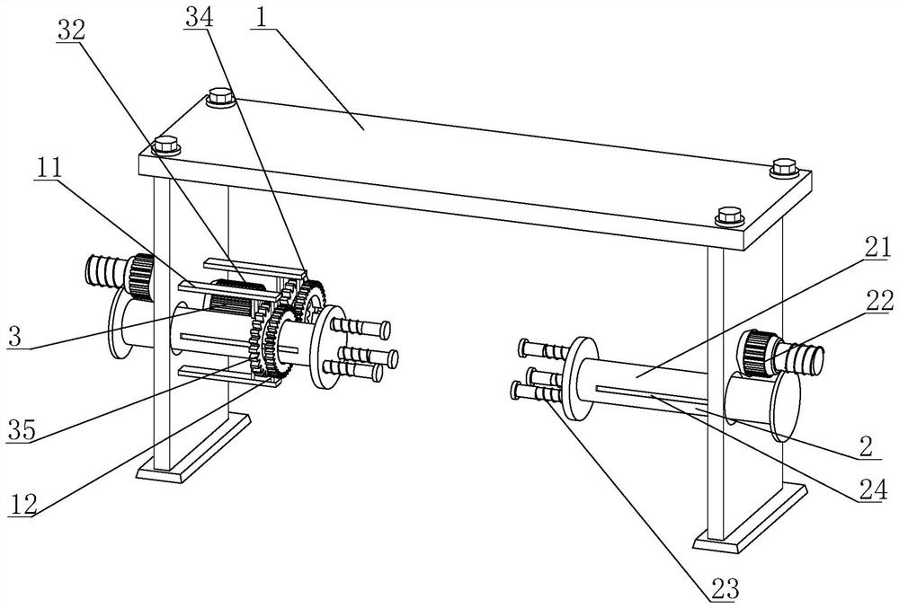
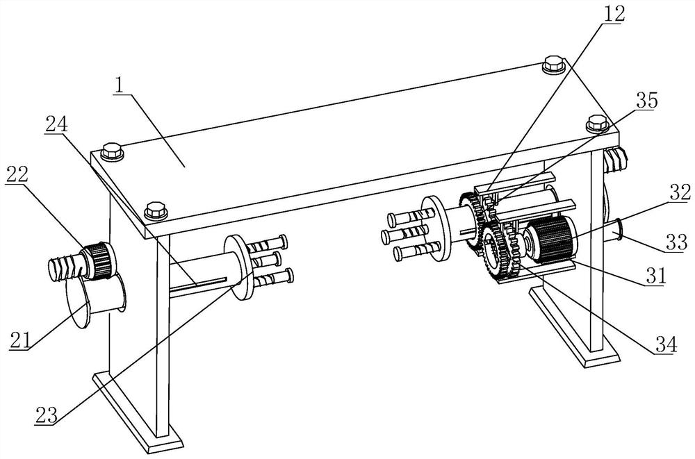
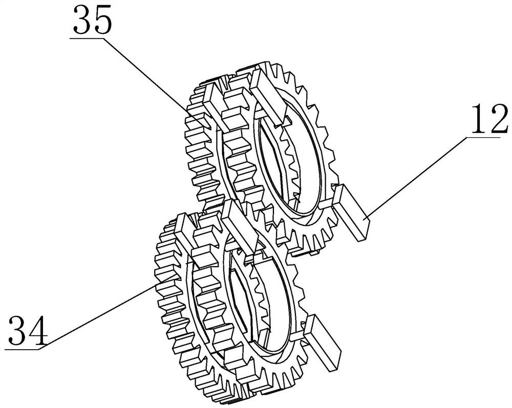
[0021] Such as Figure 1-Figure 4 As shown, an engine cylinder head overturning device includes a mounting frame 1, and two opposite clamping mechanisms 2 that can precisely control the length for clamping the engine cylinder head are provided slidingly inside the mounting frame 1, On the side of the clamping mechanism 2, an overturning mechanism 3 for rotating the clamping mechanism 2 and capable of precisely controlling the overturning angle is provided.

[0022] ...


PUM


Abstract

The invention relates to an engine cylinder head overturning device, which includes a mounting frame, and two opposite clamping mechanisms that can precisely control the length for clamping the engine cylinder head are slidingly arranged inside the mounting frame. The side of the clamping mechanism is provided with an overturning mechanism for rotating the clamping mechanism, which can precisely control the overturning angle. The present invention installs a worm at the front end of the first motor, drives the main rod to move through the rotation of the worm, realizes the precise control of the moving length of the main rod, makes the clamping force of the main rod to the engine cylinder head more accurate, and avoids the Too much or too little movement of the main rod will cause unnecessary damage to the engine cylinder head and insufficient clamping force. The present invention also sets two sets of gear sets with different numbers of teeth, and realizes the fineness of different rotation angles through different gears. The control is used to deal with processing devices in different directions and different needs, so as to facilitate the repair and processing of corresponding processing devices.

Description

technical field [0001] The invention relates to the field of engine cylinder head repair production and processing, in particular to an engine cylinder head turning device. Background technique [0002] During the repair process of the automobile engine cylinder head, the engine cylinder head needs to be clamped and flipped to cooperate with the repairing processing device to process and repair each surface or corner of the engine cylinder head. [0003] At present, the clamping of the engine cylinder head is carried out by moving the clamping rod, but there is no precise control of the moving length of the clamping rod, which may easily cause inaccurate movement of the clamping rod, and the engine cylinder head cannot be clamped or clamped. Too much movement of the holding rod will cause damage to the engine cylinder head by clamping it too tightly. At the same time, when the engine cylinder head is turned over, the motor rotation friction is used to drive the clamping rod ...

Claims


Application Information

Patent Timeline
Patent Type & Authority Patents(China)
IPC IPC(8): B25H1/10B25H1/08
CPCB25H1/08B25H1/10
Inventor 程敬卿刘泽军
Owner WUHU DINGHENG MATERIAL TECH
Why Eureka
Try Eureka