A rotary robot joint

A robot joint and robot technology, applied in the field of robotics, can solve problems such as large restrictions on the effective rotation angle of robot joints, restrictions on the range of swing angles, and large internal leakage.

Active Publication Date: 2021-04-23
DONGGUAN UNIV OF TECH
View PDF10 Cites 0 Cited by
  • Summary
  • Abstract
  • Description
  • Claims
  • Application Information

AI Technical Summary

Problems solved by technology

The former adopts a swing hydraulic cylinder, which has a large internal leakage, and the swing angle range is also limited; the latter adopts a triangular structure transmission, which makes the effective rotation angle of the robot joint more limited, generally within the range of 135°, and the hydraulic cylinder The size of the force arm of the output force changes in real time, resulting in the maximum effective torque of the joint being a variable value

Method used


Image

  • A rotary robot joint
  • A rotary robot joint
  • A rotary robot joint

Examples


Embodiment Construction

[0019] The following will clearly and completely describe the technical solutions in the embodiments of the present invention with reference to the accompanying drawings in the embodiments of the present invention. Obviously, the embodiments described below are some, not all, embodiments of the present invention. Based on the embodiments of the present invention, all other embodiments obtained by persons of ordinary skill in the art without making creative efforts belong to the protection scope of the present invention.

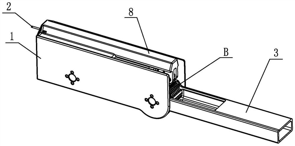
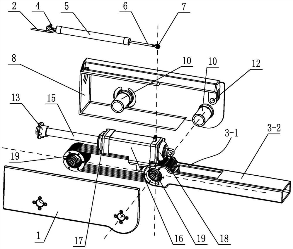
[0020] combine figure 1 and figure 2 As shown, a rotary robot joint includes a robot arm 8, a robot arm 3, a double-piston rod hydraulic cylinder A and a rotary motion mechanism B;

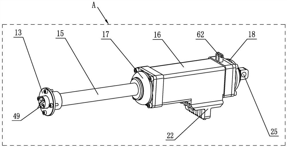
[0021] The robot arm 8 is a hollow arm, and the double piston rod hydraulic cylinder A and the rotary motion mechanism B are arranged in the robot arm 8. The hydraulic cylinder body 16 of the double piston rod hydraulic cylinder A is connected with the rotary motion mechanism B...


PUM


Abstract

A rotary robot joint, which includes a robot arm, a robot forearm, a double-piston rod hydraulic cylinder and a rotary motion mechanism; the robot big arm is a hollow arm, and the double-piston rod hydraulic cylinder and the rotary motion mechanism are arranged Inside, the hydraulic cylinder body of the double-piston rod hydraulic cylinder is connected to the rotary motion mechanism, and the two piston rods of the double-piston rod hydraulic cylinder are fixedly connected to the arm of the robot respectively. The linear motion of the hydraulic cylinder body of the cylinder is converted into the rotary motion of the rotary motion mechanism, and the output end of the rotary motion mechanism drives the robot arm to swing and rotate. Process the oil hole and the oil in and out circuit for the high and low pressure oil in and out to control the piston action of the double piston rod hydraulic cylinder. The invention has the characteristics of compact structure, large hydraulic driving force and good buffering function.

Description

technical field [0001] The invention relates to a robot, in particular to a rotary robot joint. It belongs to the application field of robot technology. Background technique [0002] The drive of robot joints mainly has three forms: motor drive, hydraulic cylinder drive, and artificial muscle drive. Among them, the hydraulic cylinder drive has the largest power-mass density, which is convenient for the high-power design of the robot joint. Traditional robot joints driven by hydraulic cylinders use swing hydraulic cylinders to output rotary motion; or use linear cylinders to drive through triangles to control the rotation of robot joints. Both approaches have their limitations. The former adopts a swing hydraulic cylinder, which has a large internal leakage, and the swing angle range is also limited; the latter adopts a triangular structure transmission, which makes the effective rotation angle of the robot joint more limited, generally within the range of 135°, and the hy...

Claims


Application Information

Patent Timeline
Patent Type & Authority Patents(China)
IPC IPC(8): B25J17/02
CPCB25J17/0258
Inventor 张超尹玲汪超王帅朱建军张兵
Owner DONGGUAN UNIV OF TECH
Why Eureka
Try Eureka