Header foaming frame

A foaming frame and header technology, applied in the field of solar header production equipment, can solve the problems of difficulty in controlling the density of foamed materials, poor insulation performance of the headers, and low foaming density, etc. Foaming effect, the effect of ensuring performance

Inactive Publication Date: 2020-02-07
HAINING YINUO ELECTRIC
View PDF6 Cites 3 Cited by
  • Summary
  • Abstract
  • Description
  • Claims
  • Application Information

AI Technical Summary

Problems solved by technology

[0002] The solar engineering header is one of the important components of the solar hot water project. It is used to collect and store solar heat. In order to ensure its thermal insulation performance, the header often needs to be foamed. At present, when the header is foamed, it needs First inflate the inner tank of the header to fully open the inner tank to avoid deformation of the inner tank during the foaming process, and

Method used


Image

  • Header foaming frame
  • Header foaming frame

Examples


Embodiment Construction

[0017] The present invention is described in further detail below:

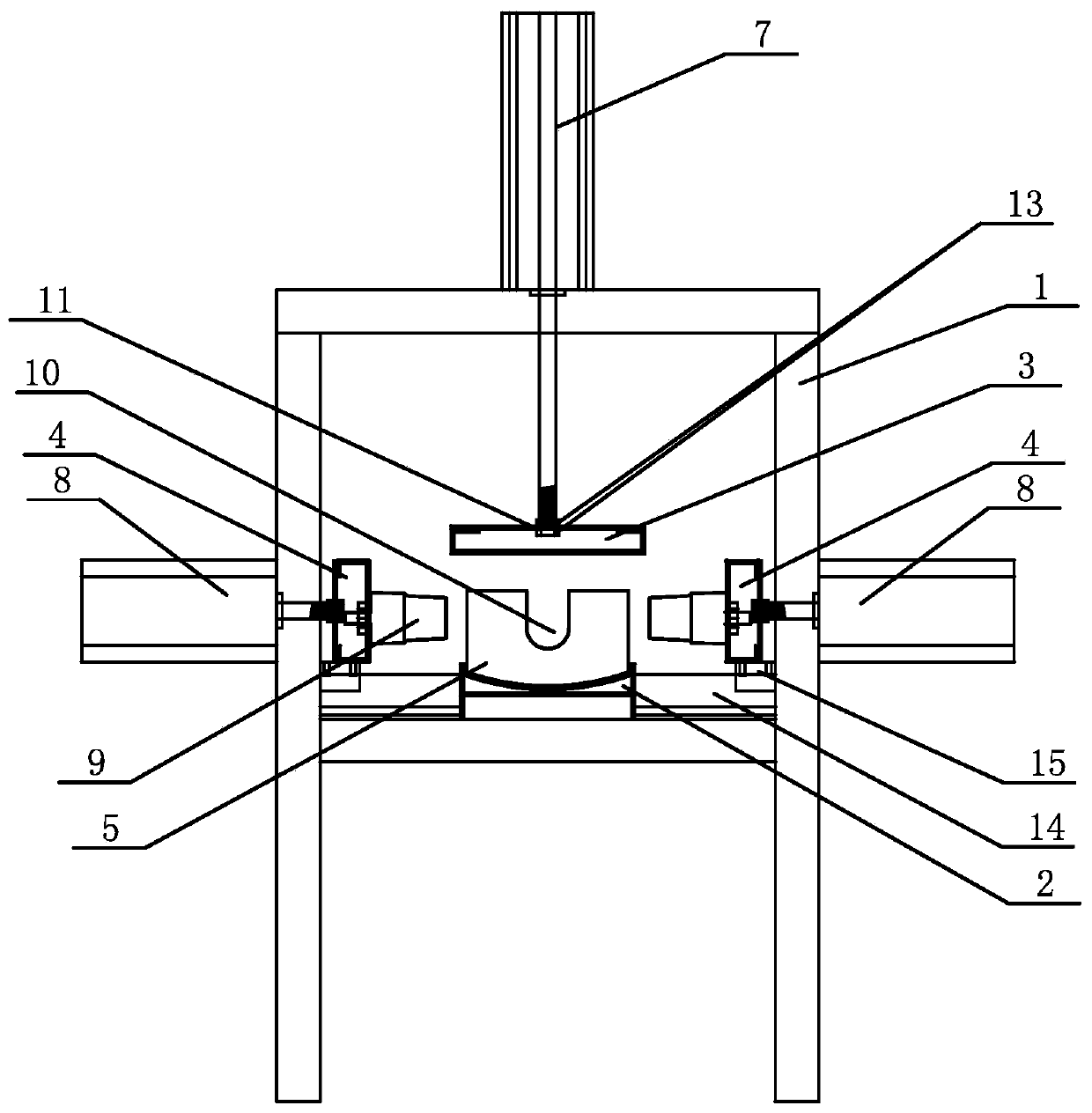
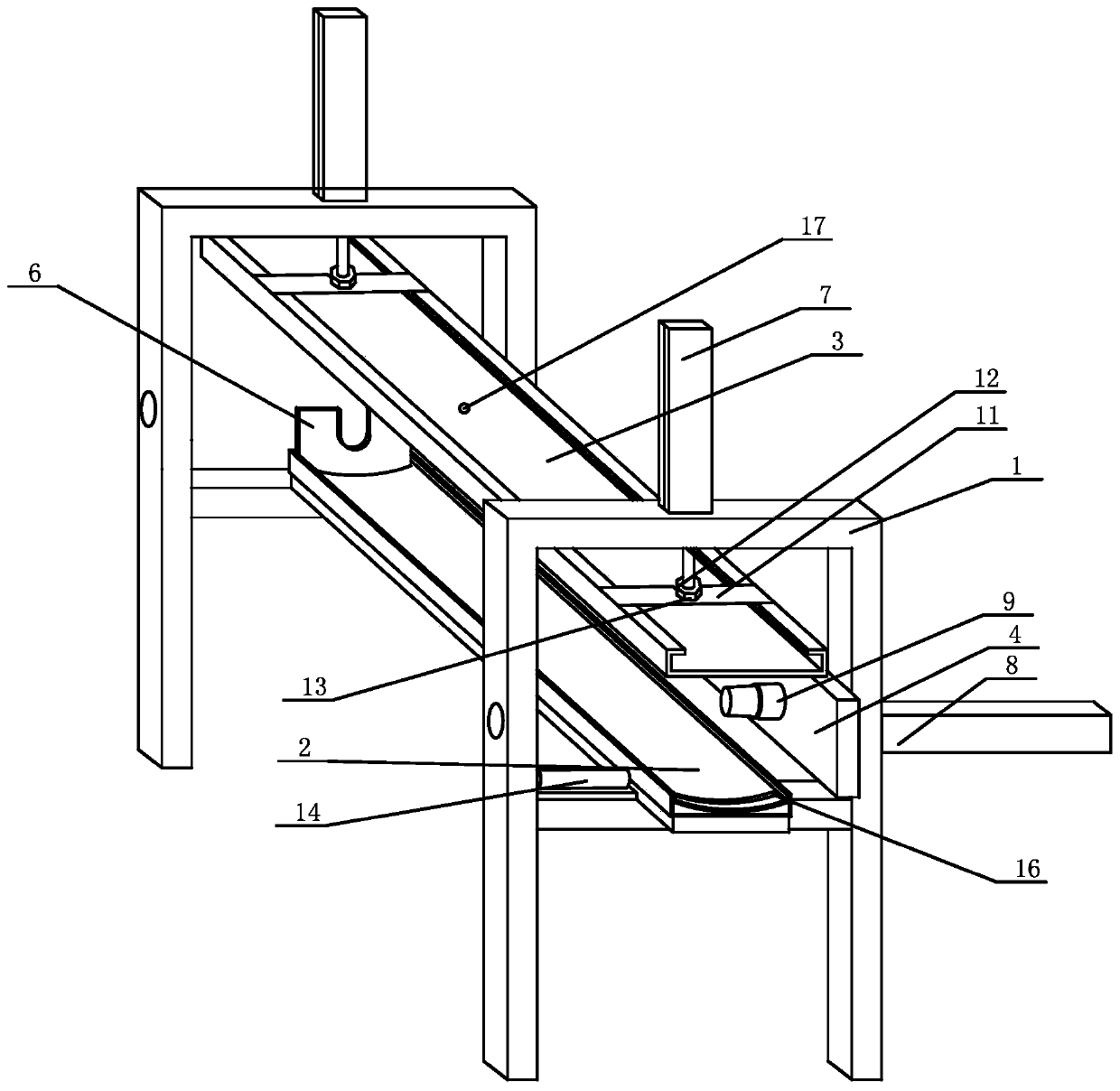
[0018] The present invention provides a header foam frame, which includes a frame 1, a base 2, an upper pressure plate 3, a side pressure plate 4, a front limiting plate 5, a rear limiting plate 6, a first cylinder 7 and a second cylinder 8, the base 2. Set horizontally on the frame 1, the upper platen 3 is located above the base 2, the first cylinder 7 is fixed on the upper end of the frame 1, the piston rod of the first cylinder 7 is connected with the upper platen 3, and the upper platen is driven by the first cylinder 7 3 can move up and down along the frame 1, and the upper pressing plate 3 is provided with a material injection hole 17 for feeding into the header, and the number of the side pressing plates 4 is two and located on the left and right sides of the base 2, The back side of the side pressure plate 4 is connected with the piston rod of the second cylinder 8, and the second cylinder 8 is fixed ...


PUM


Abstract

The invention provides a header foaming frame. The header foaming frame can be used to inject a material from the bottom of the header, can effectively guarantee the foaming density of the foaming material, and guarantees thermal insulation performance of a product. The header foaming frame comprises a frame, a bottom seat, a top pressing board, side pressing boards, a front limiting board, a rearlimiting board, a first air cylinder and a second air cylinder, wherein the bottom seat is horizontally arranged on the frame, the top pressing plate is located above the bottom seat, the first air cylinder is fixed at the upper end of the frame, a piston rod of the first air cylinder is connected with the top pressing plate, a material injection hole used for injecting the material into the header is formed in the top pressing plate, the quantity of the side pressing boards is two, the two side pressing boards are located on the left side and the right side of the bottom seat, the back surfaces of the side pressing boards are connected with a piston rod of the second air cylinder, the second air cylinder is fixed on the side face of the frame, end caps which can block connection holes intwo sides of the header are formed in the inner sides of the side pressing boards, the front limiting board and the rear limiting board are respectively and detachably arranged at two ends of the bottom seat, and positioning grooves are formed in the front limiting board and the rear limiting board.

Description

technical field [0001] The invention relates to the technical field of solar header production equipment, in particular to a header foam frame. Background technique [0002] The solar engineering header is one of the important components of the solar hot water project. It is used to collect and store solar heat. In order to ensure its thermal insulation performance, the header often needs to be foamed. At present, when the header is foamed, it needs First inflate the inner tank of the header to fully open the inner tank to avoid deformation of the inner tank during the foaming process, and then inject the foaming agent. Currently, the foaming agent is used to connect the solar heat collector tube from the side of the header The connection hole is punched in, and the material can only be injected section by section, and this foaming method makes it difficult to control the density of the foam material in each part of the header, and the overall foam density is low, which will...

Claims


Application Information

Patent Timeline
IPC IPC(8): B29C44/34
CPCB29C44/35
Inventor 虞建忠杨以杰
Owner HAINING YINUO ELECTRIC
Why Eureka
Try Eureka