Curved screen magnetron sputtering assembly

A technology of magnetron sputtering and curved screen, applied in sputtering plating, ion implantation plating, metal material coating process, etc. Uniformity and other issues, to achieve the effect of stable and accurate operation, low cost, and uniform sputtering deposition

Pending Publication Date: 2020-02-07
XIANGTAN HONGDA VACUUM TECH CO LTD
View PDF13 Cites 3 Cited by
  • Summary
  • Abstract
  • Description
  • Claims
  • Application Information

AI Technical Summary

Problems solved by technology

However, for curved substrates such as curved mobile phone screens, twin parallel targets cannot make the sputtered particles evenly deposited on the substrate
[0004] In addition, for the existing umbrella turret or revolving substrate frame, the substrate frame rotates in the way of revol

Method used


Image

  • Curved screen magnetron sputtering assembly
  • Curved screen magnetron sputtering assembly
  • Curved screen magnetron sputtering assembly

Examples


Embodiment Construction

[0030] A curved screen magnetron sputtering assembly provided by the present invention will be further described in detail and completely below in conjunction with the embodiments. The embodiments described below are exemplary only for explaining the present invention and should not be construed as limiting the present invention.

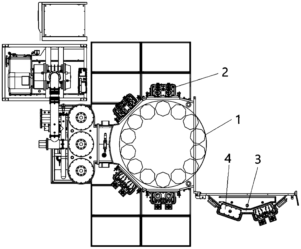
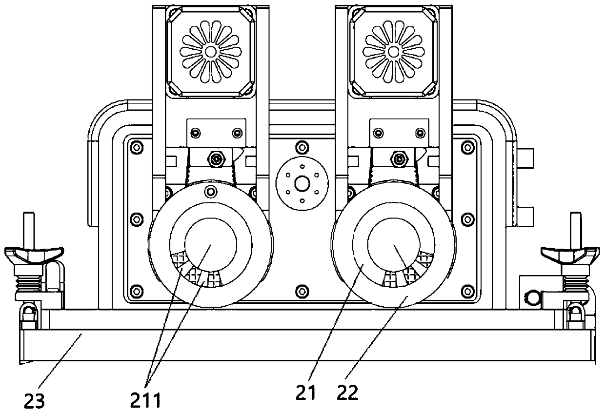
[0031] A curved screen magnetron sputtering component, such as Figure 2 to Figure 9 As shown, it includes a male rotation umbrella turret 1 and multiple sets of cathode assemblies 2, and the rotation umbrella turret 1 and multiple sets of cathode assemblies 2 are installed in the coating chamber in the corresponding coating box, and the coating box is provided with a The door body 3 of the coating chamber is opened or closed, and a molecular pump is provided on the wall of the coating box for vacuuming the coating chamber to facilitate the subsequent vacuum coating operation. The above-mentioned vacuuming operation can adopt the existing vacuuming...


PUM


Abstract

The invention provides a curved screen magnetron sputtering assembly. The curved screen magnetron sputtering assembly comprises a revolution and rotation umbrella rotating frame and a plurality of sets of cathode assemblies, wherein the plurality of sets of cathode assemblies are not in contact with the revolution and rotation umbrella rotating frame; the plurality of sets of cathode assemblies are distributed in the circumferential direction of the revolution and rotation umbrella rotating frame; each set of cathode assemblies comprises two cathode devices; each cathode device comprises a magnetic rod; the magnetic field directions of the two magnetic rods of each set of cathode assemblies can be adjusted; the revolution and rotation umbrella rotating frame comprises a rotation frame anda plurality of sets of revolution and rotation frames used for loading substrates; the rotation frame is arranged in a mode of being capable of rotating around the central axis of the rotation frame;the revolution and rotation frames are mounted on the rotation frame in a mode of being capable of rotating; and the plurality of sets of revolution and rotation frames are driven to revolute around the central axis when the rotation frame rotates. According to the curved screen magnetron sputtering assembly, a substrate frame drives the substrates to rotate and revolute at the same time, the magnetic field directions of the two magnetic rods of each set of cathode assemblies can be adjusted, and sputtering deposition is more uniform.

Description

technical field [0001] The invention relates to the technical field of coating production, in particular to a curved screen magnetron sputtering component. Background technique [0002] Magnetron sputtering means that electrons collide with argon atoms in the process of flying to the substrate under the action of an electric field, so that they are ionized to generate Ar positive ions and new electrons; the new electrons fly to the substrate, and the Ar ions in the electric field Under the action, it accelerates to the cathode target, and bombards the target surface with high energy to cause sputtering of the target. Among the sputtered particles, neutral target atoms or molecules are deposited on the substrate to form a thin film. [0003] When twin targets are used in the existing magnetron sputtering process, such as figure 1 As shown, the magnetic field directions C of the corresponding two sets of magnetic rods are parallel, see figure 1 , the resulting sputtered part...

Claims


Application Information

Patent Timeline
IPC IPC(8): C23C14/35C23C14/50
CPCC23C14/352C23C14/3407C23C14/505
Inventor 孙桂红祝海生黄乐陈立唐洪波唐莲凌云徐璐
Owner XIANGTAN HONGDA VACUUM TECH CO LTD
Why Eureka
Try Eureka