Laser radar optical receiving system

A laser radar and optical receiving technology, applied in the field of laser radar optical receiving system, can solve the problems of high price of multi-line laser radar, cumbersome arrangement of multiple detectors, and limited development, so as to promote civilian use, small distortion, The effect of meeting the miniaturization requirements

Pending Publication Date: 2020-02-07
福建海创光电技术股份有限公司
View PDF0 Cites 1 Cited by
  • Summary
  • Abstract
  • Description
  • Claims
  • Application Information

AI Technical Summary

Problems solved by technology

The main reason for its high cost is that how many lines of lidar need to correspond to how many detectors, and the arrangement of multiple detectors is cumbersome, and the price is relatively expensive, so the price of multi-line lidar is expensive, and to a certain extent limit the development of civil

Method used


Image

  • Laser radar optical receiving system
  • Laser radar optical receiving system
  • Laser radar optical receiving system

Examples


Embodiment Construction

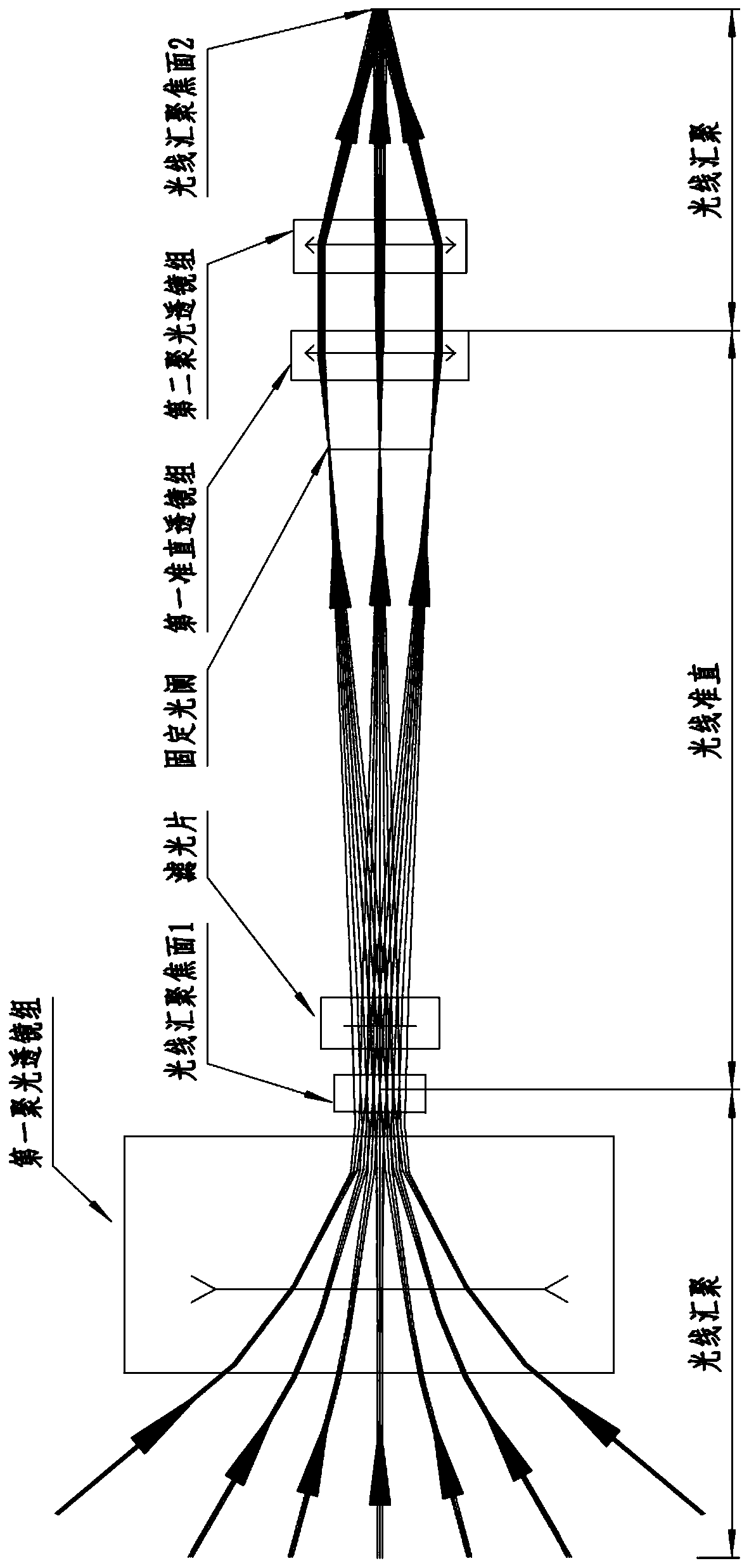
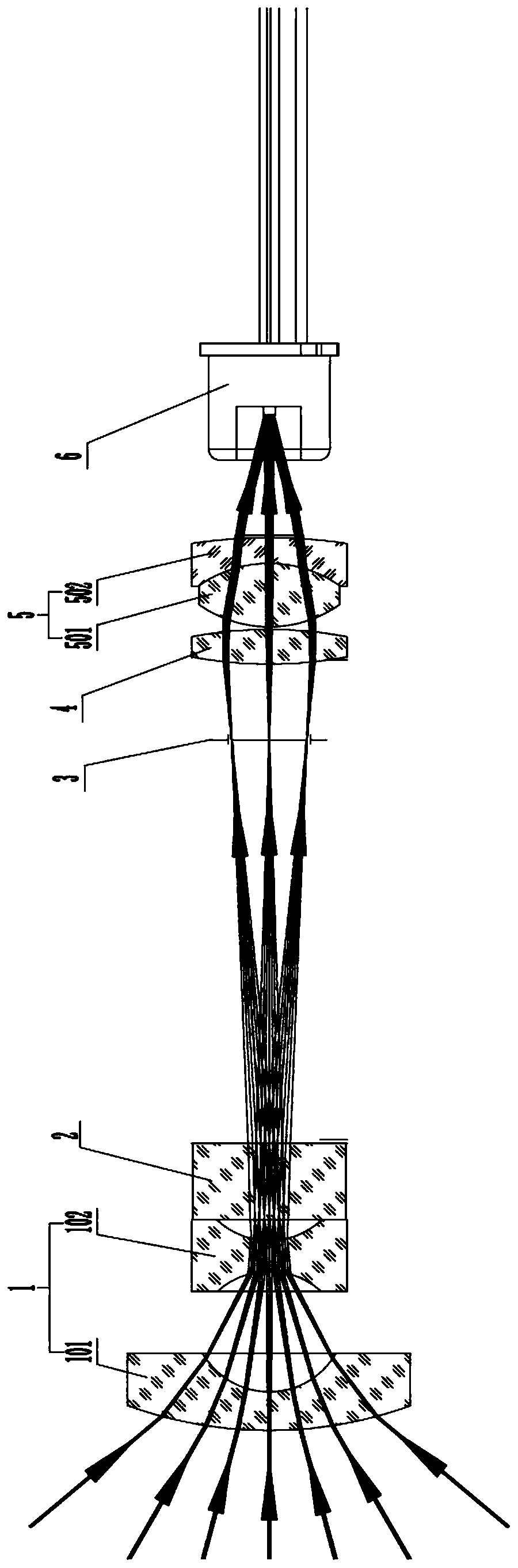
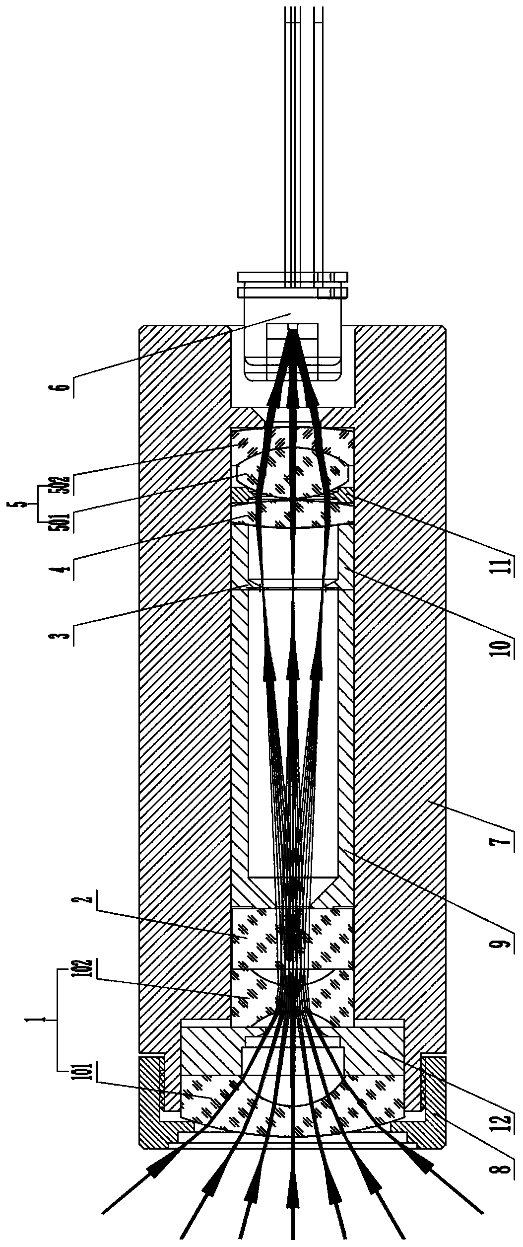
[0031] like Figures 1 to 3 As shown in one of them, the laser radar optical receiving system of the present invention includes:

[0032] The lidar receiving lens is used to gather the incident light signal and focus the output;

[0033] The detection unit 6 is used to receive the optical signal output by the lidar receiving lens focusing;

[0034] The focal plane formed by the laser radar receiving lens is located on the receiving surface of the detection unit 6 and the focal plane is equal to or smaller than the photosensitive element area of ​​the receiving surface of the detection unit 6 .

[0035] Wherein, the lidar receiving lens includes a first condenser lens group 1, an optical filter 2, a fixed diaphragm 3, a first collimator lens group 4 and a second condenser lens group 5 arranged sequentially along the optical path, Wherein, the first condenser lens group 1 is a negative power condenser lens group, and the second condenser lens group 5 is a positive power conden...


PUM


Abstract

The invention discloses a laser radar optical receiving system. The laser radar optical receiving system, comprises: a laser radar receiving lens used for converging an incident optical signal and focusing and outputting the incident optical signal; and a detection unit used for receiving an optical signal focused and output by the laser radar receiving lens, wherein a focal plane formed by focusing of the laser radar receiving lens is located on the receiving surface of the detection unit and is equal to or smaller than the area of the photosensitive element of the receiving surface of the detection unit. The laser radar lens in the system converges and collimates large-view-field angle information through the lens, and converges the large-view-field angle information to the laser radar receiving system of a single detector. Height information receiving perpendicular to a laser radar transmitting plane is met, the number of detectors used in a laser radar system is reduced, and the miniaturization requirement of laser radar is met. Besides, a single detection element is adopted, so that the packaging size can be miniaturized, the problem of high cost of a linear array or array detection unit is solved, and the laser radar is promoted to be truly civilian.

Description

technical field [0001] The invention belongs to the field of laser communication devices, in particular to the field of laser communication devices that can be used for unmanned vehicles, robot detection, unmanned aerial vehicle detection, automatic sweeping machines and other equipment, and specifically relates to a laser radar optical receiving system. Background technique [0002] Lidar is a radar that works in the optical frequency band. It uses the electromagnetic wave in the optical frequency band to first transmit a detection signal to the target, and then reflects it back to receive the same wave signal and transmit the signal for information processing, so as to obtain the position of the target (distance , azimuth and altitude), motion status (speed, attitude) and other information to realize the detection, tracking and identification of targets. Because lidar has high progress, strong anti-interference ability, simple structure and convenient use, it has been wide...

Claims


Application Information

Patent Timeline
Patent Type & Authority Applications(China)
IPC IPC(8): G01S7/486G01S7/4912G01S7/481
CPCG01S7/486G01S7/4912G01S7/4816
Inventor 罗联镜丁广雷汪兆永李明
Owner 福建海创光电技术股份有限公司
Why Eureka
Try Eureka