
Positioner capable of rotating at multiple angles

A positioner, multi-angle technology, applied in the direction of control using feedback, can solve the problems of low repeated positioning, increased motor power, and energy waste.

Inactive Publication Date: 2014-02-12
INST OF MICROELECTRONICS CHINESE ACAD OF SCI +1
View PDF6 Cites 4 Cited by
  • Summary
  • Abstract
  • Description
  • Claims
  • Application Information

AI Technical Summary

Problems solved by technology

For example, the GCD electronically controlled rotary table series of Daheng New Era Technology Co., Ltd. is driven by a two-phase stepping motor, and can realize the rotary motion of the rotary table with the worm gear drive. The disadvantage of this type of product is that it is bulky and heavy. The worm gear transmission with a large reduction ratio, the turntable speed is low, and the maximum speed is 3RPM
In addition, the DRTM series electric rotary table of OWIS company in Germany is driven by a stepping motor or a servo motor, and is driven by a synchronous belt to realize the rotary positioning of the rotary table. Larger, with obvious heat generation and low positioning accuracy
In addition, in the prior art, there is another method that omits the mechanical transmission link and uses a hollow shaft motor, such as the AH4K series 5-phase hollow shaft stepping motor of Autonics in South Korea, to directly connect the optical element to the hollow shaft to realize the positioning of the optical device. The disadvantage of this type of technology is that it is difficult to achieve a large amount of light transmission. The maximum light transmission amount of the AH4K series 5-phase hollow shaft stepper motor is a circle with a diameter of 9mm. The motor used in this type of technology is special and expensive. If you want to Increasing the clear aperture can only increase the size of the motor and increase the power of the motor, while the load is only an optical device with a small mass. This technology feels like a "big cow pulling a small cart", which is a waste of energy
To sum up, the rotary positioning platform in the prior art has a large volume and mass, some technologies have a small amount of light transmission and are expensive, and some technologies have low repetitive positioning and large heat generation and vibration, which is not conducive to the system integration of optical instruments

Method used


Image

  • Positioner capable of rotating at multiple angles
  • Positioner capable of rotating at multiple angles
  • Positioner capable of rotating at multiple angles

Examples


Embodiment

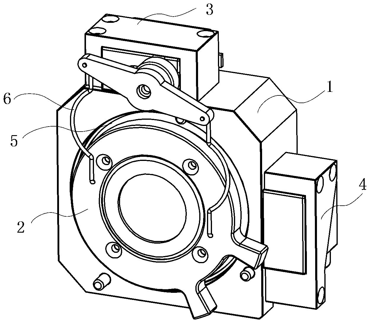
[0059] Taking the multi-angle rotary locator with 2 fixed locating pins and 1 movable locating pin as an example, the multi-angle rotary locator provided by the present invention and its working principle are as follows:

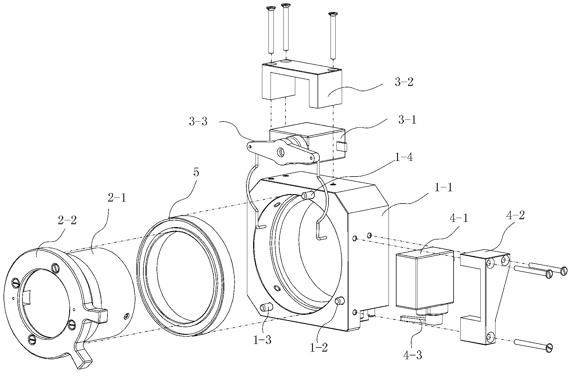
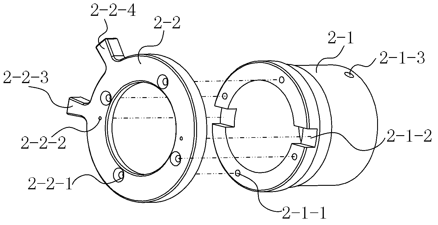
[0060] Such as figure 1 As shown, the multi-angle rotary positioner of the present invention includes a base 1 , a hollow rotating body 2 , a driving assembly 3 , a control assembly 4 , a bearing 5 and a connecting rod 6 . Wherein, the driving assembly 3 is located at the upper edge of the base 1 , and the control assembly 4 is located at the right edge of the base 1 . The bearing 5 is fixed inside the base 1, and its outer ring and the inner ring of the base 1 are interference fit. The hollow rotating body 2 is fixed on the inner ring of the bearing 5, and the hollow rotating body 2 and the inner ring of the bearing 5 are also interference fit. Through the above assembly, the outer ring of the bearing can be fixed with the base 1, and the inner ring of th...


PUM


Abstract

The invention discloses a positioner capable of rotating at multiple angles, and belongs to the technical field of optical device adjusting devices. The positioner capable of rotating at multiple angles can automatically control the rotation angle of an optical device. The positioner capable of rotating at multiple angles comprises a base, a driving assembly, a bearing, a hollow rotary body, a first connecting rod and a second connecting rod. The positioner capable of rotating at multiple angles is compact in size, large in light flux, accurate in positioning, high in repeatability, and capable of automatically controlling the light-permeable optical device to rotate.

Description

technical field [0001] The invention relates to the technical field of optical device adjustment devices, in particular to a multi-angle rotary positioner capable of automatically controlling the rotation angle of optical devices. Background technique [0002] In the application of optical detection equipment and instruments, it is sometimes necessary to automatically control the optical components in them to rotate to multiple different angles, thereby creating multiple different measurement conditions. For example, when using ellipsometry to measure the film thickness and reflectivity of a wafer, it is necessary to rotate the polarizer to 0°, 45°, 90° and 135° respectively. Such requirements often have strict requirements on the accuracy and repeatability of the rotation angle positioning. [0003] In the prior art, the automatic angle control of optical detection equipment and instruments can be realized by using stepper motors and servo motors as driving components. Fo...

Claims


Application Information

Patent Timeline
IPC IPC(8): G05D3/12
Inventor 吴文镜李国光叶龙茂赵江艳
Owner INST OF MICROELECTRONICS CHINESE ACAD OF SCI
Learn More