
Air-suction type seeder for small and medium-sized seeds

A small-grain, air-suction technology, applied in the field of agricultural machinery, can solve the problems of unsatisfactory seed adsorption effect, blockage of seeding wheel, increase of manufacturing cost, etc. Effect

Active Publication Date: 2020-02-11
KUNMING UNIV OF SCI & TECH
View PDF2 Cites 2 Cited by
  • Summary
  • Abstract
  • Description
  • Claims
  • Application Information

AI Technical Summary

Problems solved by technology

[0003] At present, due to the long airway distance of conventional air suction seeders, and the air suction generally adopts fast airflow, when the airflow passes through the airway quickly, the shaft airway will have serious loss along the way. If multiple seeding wheels are simultaneously The seeding wheel at the end of the airway has poor seed suction effect; for a single seeding wheel, due to the large diameter of the airway of the rotating shaft, the design diameter of the seeding wheel is large, and each airway connected to the hole Due to the long distance from the air passage of the rotating shaft, the adsorption effect on the seeds is not ideal. To avoid the above problems, a high-power air pump is required, which will excessively increase the manufacturing cost and cannot be used in normal agricultural work.
At the same time, due to the different sizes of the seeds, smaller seeds may be stuck in the air passage connected to the suction hole, causing the seed wheel to be blocked and affecting the seed metering efficiency of the seed meter.

Method used


Image

  • Air-suction type seeder for small and medium-sized seeds
  • Air-suction type seeder for small and medium-sized seeds
  • Air-suction type seeder for small and medium-sized seeds

Examples


Embodiment 1

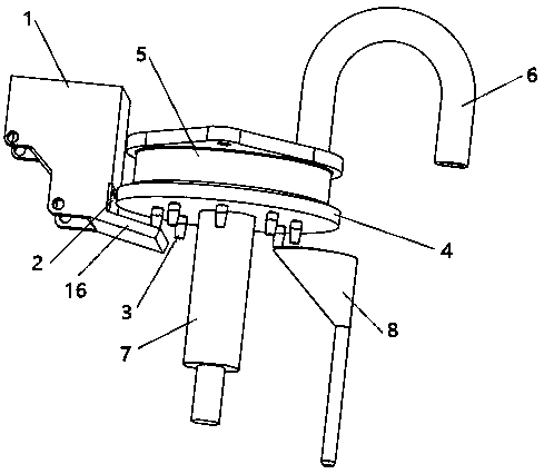
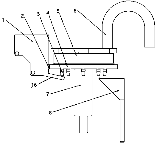
[0032] Such as figure 1 , figure 2 and Figure 5 As shown, the small and medium-sized seed air suction planter includes a seed box 1, a seeding tray 4, a negative pressure air chamber housing 5, and a seeding tube 8. The top two sides of the negative pressure air chamber housing 5 are provided with outwardly extending ears. The plate is fixed on the planter frame by ear plates and bolts. The negative pressure air chamber housing 5 is provided with an annular air chamber 17, and the top of the negative pressure air chamber housing 5 is provided with a negative pressure air passage communicating with the air chamber 17 6. The negative pressure air passage 6 is a U-shaped tube, and the other end is connected with a negative pressure pump, which can generate negative pressure in the air chamber 17. The bottom of the negative pressure air chamber housing 5 and the seeding disc 4 are connected by a snap-in type, and the seeding disc 4 can be The housing 5 rotates relative to the nega...

Embodiment 2

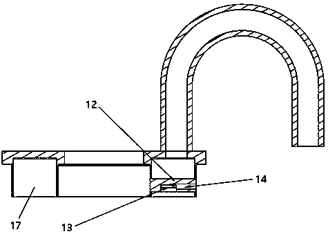
[0035] Such as image 3 with Figure 4 As shown, the airflow barrier 12 is provided with a groove in the middle of the bottom surface, and a photoelectric sensor 13 is installed in the groove. One side of the groove is connected to the outside through a through hole 14 which is used for the wire arrangement and balance release of the photoelectric sensor 13 The pressure groove 18 and the outside atmospheric pressure make it easier for the seed particles to fall from the seed suction nozzle. In this example, the photoelectric sensor 13 is a patch type photoelectric sensor, and the photoelectric sensor 13 is facing the seed suction air passage 10, and is used to detect the luminous flux of the medium hole 11 of the seed suction nozzle 3 to determine whether the hole 11 is filled with seeds, namely According to the information fed back by the photoelectric sensor 13, it is determined whether the broadcast is missed. When the hole 11 has been filled with seeds, the amount of light ...

Embodiment 3

[0037] Such as Image 6 with Figure 7 As shown, the present invention also includes a closed air nozzle 15. The closed air nozzle 15 and the seed suction nozzle 3 are alternately arranged at the bottom of the seed suction air passage 10 in a circular array. Both the closed air nozzle 15 and the seed suction nozzle 3 pass through threads. It is screwed on the bottom of the inhalation airway 10, and the middle part of the closed air nozzle 15 is a blind hole. After being installed on the inhalation airway 10, the sealing effect can be achieved. The closed air nozzle 15 and the inhalation air nozzle 3 are arranged at intervals to increase the relative The arrangement distance between two adjacent seed suction nozzles 3 can realize a variety of different row spacing sowing under the premise that the rotation speed of the seed metering plate 4 is unchanged, and meet the different agronomic requirements of different seeds.


PUM


Abstract

The invention discloses an air-suction type seeder for small and medium-sized seeds, and belongs to the technical field of agricultural machinery. The air-suction type seeder for small and medium-sized seeds comprises a seed box, a seed metering disc, a negative pressure air chamber outer shell and a seed metering tube, wherein the negative pressure air chamber outer shell is fixedly mounted on amachine frame of the seeder; an air chamber is formed in the negative pressure air chamber outer shell; a negative pressure air passage is formed in the top of the negative pressure air chamber outershell; the seed metering disc capable of rotating relatively is arranged at the bottom of the negative pressure air chamber outer shell; the seed metering disc is driven to rotate by a motor; seed suction air passages are uniformly formed in the seed metering disc in an annular array; seed suction air nozzles are mounted at the bottom ends of the seed suction air passages; the seed box and the seed metering tube are respectively and fixedly mounted on two sides of the seed metering disc; a seed filling slideway is formed in an outlet at the bottom of the seed box; and an air flow blocking piece is mounted on the side wall of the air chamber. The seeder utilizes a negative pressure seed suction mode to carry out seed delivery, the delivery is stable and efficient, and the phenomena of seeddamage and missed sowing and resowing are effectively reduced, and thus the seed metering efficiency of the seeder is guaranteed.

Description

Technical field [0001] The invention relates to the field of agricultural machinery, in particular to an air suction planter for small and medium grain seeds. Background technique [0002] With the rapid development of domestic agricultural machinery seeding technology, the requirements for precision seeding are getting higher and higher. According to the requirements of modern agricultural technology, the seeder should be as versatile as possible, that is, it can meet the seeding needs of multiple seeds at the same time. Small agricultural machinery can be better promoted to farmers to reduce labor intensity and improve planting efficiency, and should have an automatic detection function to reduce the missed rate of planters and reduce farmers' losses. [0003] At present, conventional air-suction seeders have a long airway distance and generally use fast airflow. When the airflow passes through the airway quickly, the shaft airway will have serious loss along the way. If multiple...

Claims


Application Information

Patent Timeline
Patent Type & Authority Applications(China)
IPC IPC(8): A01C7/04
CPCA01C7/042
Inventor 赖庆辉李俊宏
Owner KUNMING UNIV OF SCI & TECH
Learn More