Lifting and moving mechanism for physiotherapy device

A mobile mechanism and physiotherapy equipment technology, applied in physical therapy, therapy, light therapy, etc., can solve problems such as troublesome maintenance, irrationality, and multiple functions, and achieve the effect of easy replacement, easy adjustment, and simple structure

Inactive Publication Date: 2020-02-11
叶绪华
View PDF0 Cites 6 Cited by
  • Summary
  • Abstract
  • Description
  • Claims
  • Application Information

AI Technical Summary

Problems solved by technology

[0002] In the existing medical physiotherapy equipment, such as infrared physiotherapy, massage physiotherapy or magnetic therapy, etc., it is generally to directly install the above-mentioned functional parts on the bed body to realize its corresponding function, which generally can only realize a single function, and some All the above-mentioned equipments are integrated on the bed body in the multifunctional equipment to improve the use function, but this kind of combined bed body has many functions and too many parts on the bed body, so that it is not easy to use. Reasonable, and with too many functions, it is easy to be damaged, the service life will be greatly reduced, and maintenance is troublesome;
[0003] At the same time, it is not ideal to install functional equipment on the bed body in the existing functional beds.

Method used


Image

  • Lifting and moving mechanism for physiotherapy device
  • Lifting and moving mechanism for physiotherapy device
  • Lifting and moving mechanism for physiotherapy device

Examples


Embodiment

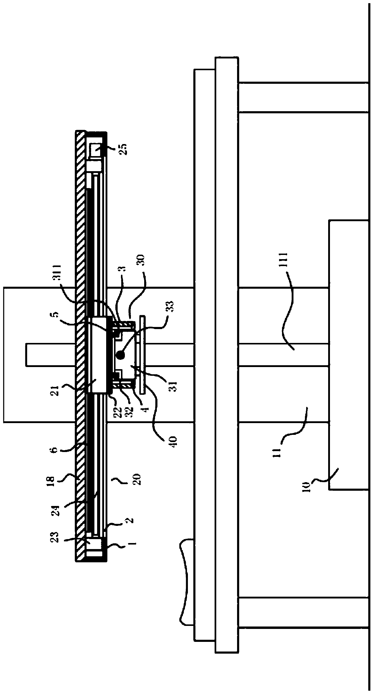
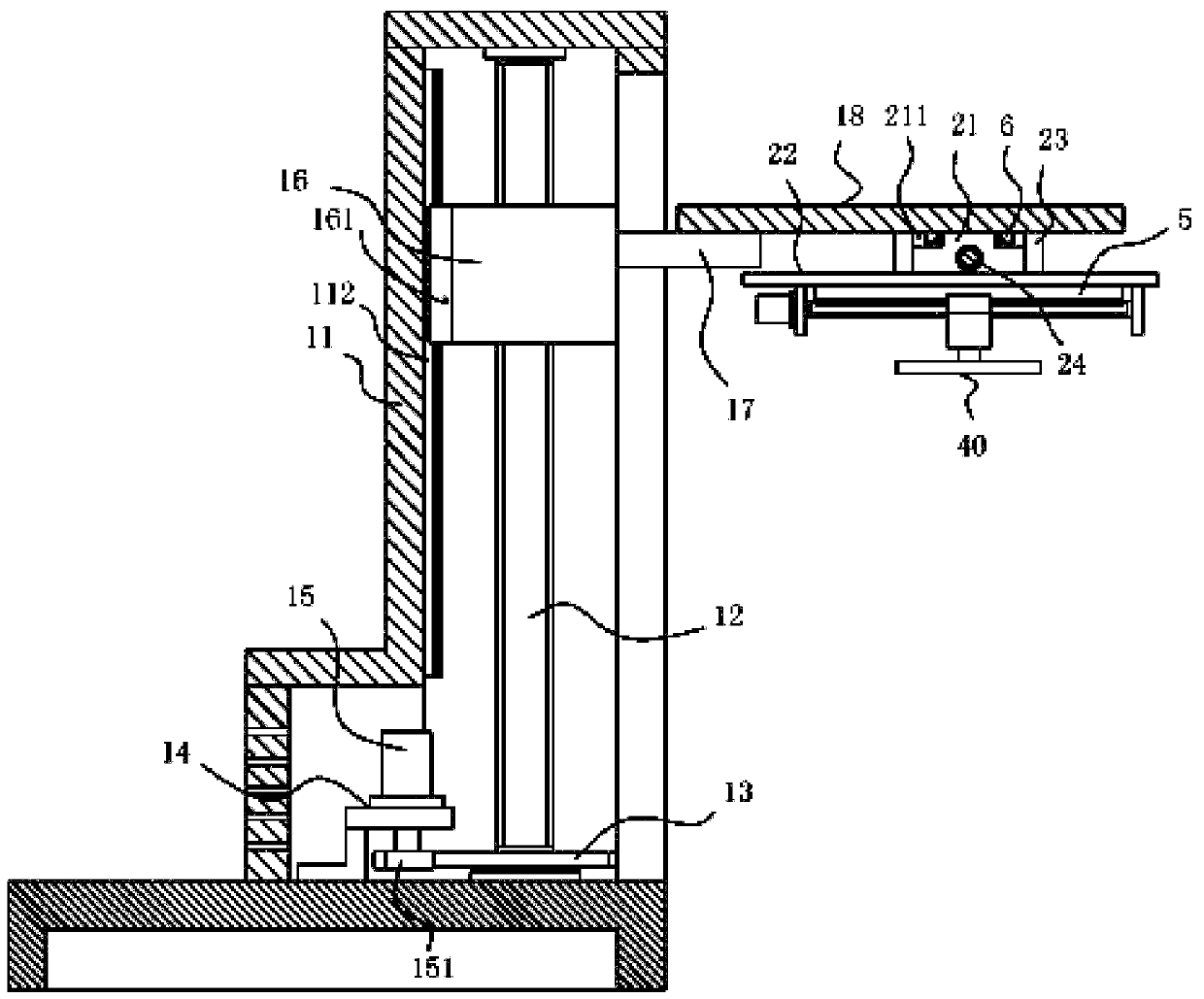
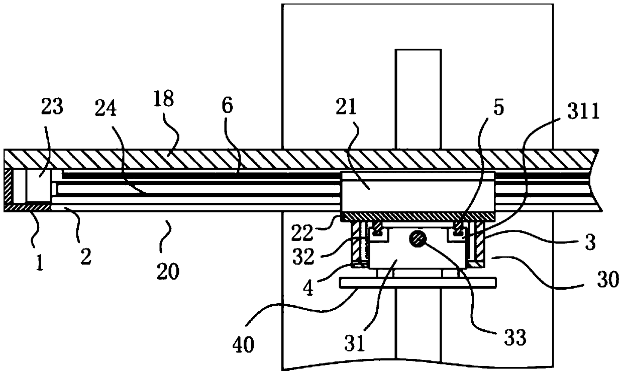
[0021] Example: see Figure 1 to Figure 3 As shown, a lifting and moving mechanism for physical therapy equipment includes a base 10, a main supporting shell 11 is fixed on the top surface of the base 10, and a main vertical screw 12 is inserted in the main supporting shell 11, and the main vertical screw The top of 12 is hinged on the top plate of main supporting shell 11 by bearing, and the bottom end of main vertical screw rod 12 is hinged on the top plate of base 10 by bearing, and the bottom of main vertical screw rod 12 is fixed with transmission gear 13, and the bottom of base 10 The rear top surface of the top plate is fixed with a motor frame 14, the top surface of the top plate of the motor frame 14 is fixed with a lift servo motor 14, and the output shaft of the lift servo motor 15 passes through the bottom surface of the top plate of the motor frame 14 and is fixed with a drive gear 151 , the driving gear 151 meshes with the transmission gear 13;

[0022] The main...


PUM


Abstract

The invention discloses a lifting and moving mechanism for a physiotherapy device. The lifting and moving mechanism comprises a base, a main support housing is fixed to the top surface of the base, amain vertical screw is inserted and sleeved into the main support housing, the top end of the main vertical screw is hinged to a top plate of the main support housing through a bearing, the bottom endof the main vertical screw is hinged to a top plate of the base through the bearing, a transmission gear is fixed to the lower part of the main vertical screw, and a motor frame is fixed to the top surface of the rear part of the top plate of the base. The lifting and moving mechanism can be placed next to a bed body, a main mounting plate is located above the bed body, different physiotherapy effects can be achieved through different functional components mounted on the main mounting plate, the physiotherapy of different parts of a user can be achieved through up-down adjustment, lateral adjustment, and vertical adjustment of the main mounting plate, the adjustment is convenient, the functional components can be dismounted and mounted and replaced according to needs, the replacement is convenient, the structure is simple, the lifting and moving mechanism can be directly placed next to an ordinary bed, and the very convenient effect is achieved.

Description

technical field [0001] The invention relates to the technical field of medical equipment, in particular to a lifting and moving mechanism for physiotherapy equipment. Background technique [0002] In existing medical physiotherapy equipment, such as infrared physiotherapy, massage physiotherapy or magnetic therapy, etc., it is generally to directly install the above-mentioned functional parts on the bed body to realize its corresponding function, which generally can only realize a single function, and some All the above equipments are integrated on the bed body in the multifunctional equipment to improve the use function, but this kind of combined bed body has many functions and too many parts on the bed body, so that it is not easy to use. Reasonable, and with too many functions, it is easy to be damaged, the service life will be greatly reduced, and maintenance is troublesome; [0003] At the same time, it is not ideal to install the functional equipment on the bed body i...

Claims


Application Information

Patent Timeline
Patent Type & Authority Applications(China)
IPC IPC(8): A61N2/00A61H23/02A61N5/06
CPCA61H23/02A61H2201/0119A61H2201/10A61N2/00A61N5/06A61N2005/0633A61N2005/064
Inventor 叶绪华
Owner 叶绪华
Why Eureka
Try Eureka