Sealed type polishing and sanding room

A grinding room, sealed technology, used in grinding/polishing equipment, grinding/polishing safety devices, grinding machines, etc., can solve the problems of inconvenient cleaning, high fan power, affecting the surrounding environment, etc., and achieve the cost of use and maintenance. Low cost, lower maintenance costs, and comfortable working environment

Pending Publication Date: 2020-02-11
安徽正义研磨环保科技有限公司
View PDF2 Cites 2 Cited by
  • Summary
  • Abstract
  • Description
  • Claims
  • Application Information

AI Technical Summary

Problems solved by technology

The existing grinding and dust removal room also has the following disadvantages: 1. The front side of the grinding room is open, with a large air intake area, large fan power, and the problem of part of the dust spreading from the opening; 2. Part of the dust settles in the On the ground of the main body of the grinding room, there are problems of inconvenient cleaning and flying dust during cleaning; 3. During the grinding operation, depending on the shape of the product, the grinding tools are moving at any time, so the dust spreads irregularly and is difficult to capture and collect. Not only affect the health and safety hazards, but also affect the surrounding environment

Method used


Image

  • Sealed type polishing and sanding room
  • Sealed type polishing and sanding room
  • Sealed type polishing and sanding room

Examples


Embodiment 1

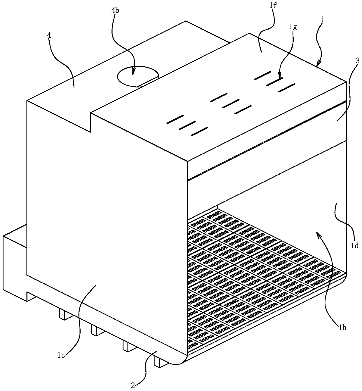
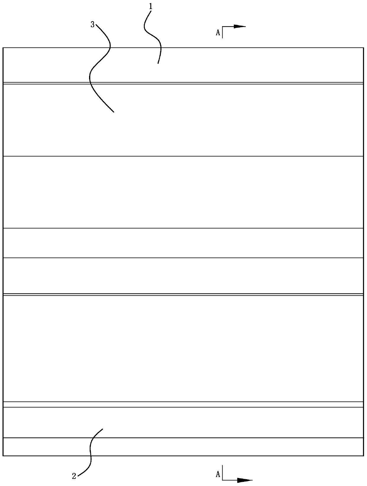
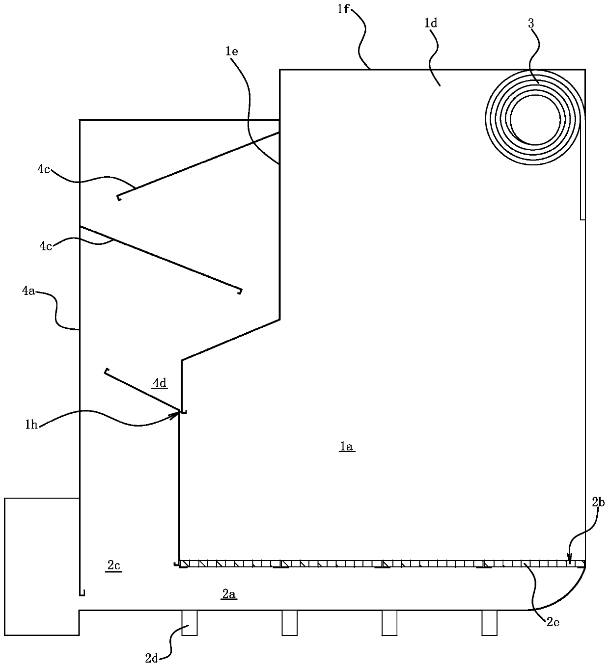
[0025] Embodiment one: if Figure 1 to Figure 3 As shown, the sealed polishing room includes a polishing room body 1 , a base 2 , an access door 3 and a separation unit 4 .

[0026] The grinding room body 1 has a grinding chamber 1a, the front side of the grinding chamber 1a is an entrance and exit 1b, and the grinding room body 1 includes a left side wall 1c, a right side wall 1d, a rear side wall 1e and a top plate 1f. There is an air inlet 1g in the top plate 1f. According to the actual situation, the air guide louver can be installed at the air inlet 1g, which can not only change the direction of the airflow, but also change the size of the airflow; the highest dust collection efficiency can be guaranteed by adjusting the direction of the airflow and the size of the airflow. .

[0027] The base 2 is placed on the ground, and the base 2 has a dust collection chamber 2a, and the top wall of the dust collection chamber 2a has a plurality of small dust inlets 2b for connectin...

Embodiment 2

[0035] Embodiment 2: The structure and principle of this embodiment are basically the same as those of Embodiment 1. The basic similarities will not be described repeatedly, and only the differences will be described. The difference is that the separation unit 4 is dry separation, and the 4a is equipped with a filter element, and there is no need to set a water storage tank 4d in the casing 4a and no need to hold water in the dust collection chamber 2a.


PUM


Abstract

The invention provides a sealed type polishing and sanding room, belongs to the technical field of operation, and solves the problem that the front side of an existing sanding room is open and part ofdust is diffused from the opening. The sealed type polishing and sanding room comprises a sanding room body with a sanding chamber, the front side of the sanding chamber is an entrance, and the sanding room body comprises a left side wall, a right side wall, a rear side wall and a top plate; the sealed type polishing and sanding room further comprises a base placed on the ground and an entrance and exit door mounted on the sanding room body; the bottom surface of the sanding chamber is covered with the base, a dust collecting cavity is formed in the base, multiple small dust inlet openings enabling the sanding chamber and the dust collecting cavity to communicate are formed in the top wall of the dust collecting cavity, and a dust outlet communicating with the dust collecting cavity is formed in the wall of the base; the entrance and exit door is located at the entrance and enables the entrance to be in an open state or a closed state; and an air inlet is formed in the top plate. Thesealed type polishing and sanding room has high dust collecting efficiency and lower use and maintenance costs, and the working environment of a sanding worker is more comfortable.

Description

technical field [0001] The invention belongs to the field of operation technology, and relates to a dust collecting device, in particular to a sealed polishing room. Background technique [0002] Polishing is a kind of surface modification technology; it is usually a processing method that uses rough abrasives to change the physical properties of the material surface through friction. When grinding a large workpiece, the workpiece is placed on the grinding table, and the grinding tool is held in hand, and the abrasive is ground against the surface of the workpiece. [0003] In order to prevent the dust from grinding from spreading, various structures of grinding dust removal rooms have been proposed. For example, a grinding and dust removal room (authorized announcement number CN203557271U) includes a grinding room body, an induced draft fan and a dust removal unit. A grinding room with high dust removal rate (application publication number CN109048673A) includes a main bo...

Claims


Application Information

Patent Timeline
IPC IPC(8): B24B27/00B24B55/06B01D47/02B01D47/06
CPCB01D47/024B01D47/06B24B27/00B24B27/0092B24B55/06
Inventor 陈美青
Owner 安徽正义研磨环保科技有限公司
Why Eureka
Try Eureka