Building concrete mixing device

A kind of mixing equipment and concrete technology, which is applied in the direction of clay preparation equipment, cement mixing equipment, unloading equipment, etc., which can solve the problems of low mixing uniformity and inconvenient unloading

Inactive Publication Date: 2020-02-11
靳继民
View PDF8 Cites 3 Cited by
  • Summary
  • Abstract
  • Description
  • Claims
  • Application Information

AI Technical Summary

Problems solved by technology

[0002] In construction engineering, concrete mixing and mixing equipment is indispensable. Traditional mix

Method used


Image

  • Building concrete mixing device
  • Building concrete mixing device
  • Building concrete mixing device

Examples


specific Embodiment approach 1

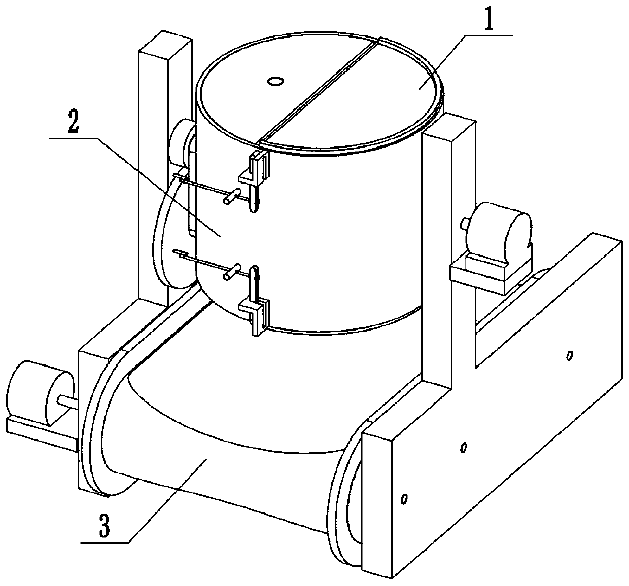
[0026] Combine below Figure 1-12 In this embodiment, a construction concrete mixing equipment includes a mixing chamber assembly 1, a stirring assembly 2 and a discharge assembly 3, the mixing chamber assembly 1 is connected to the stirring assembly 2, and the stirring assembly Body 2 is connected to discharge assembly body 3.

specific Embodiment approach 2

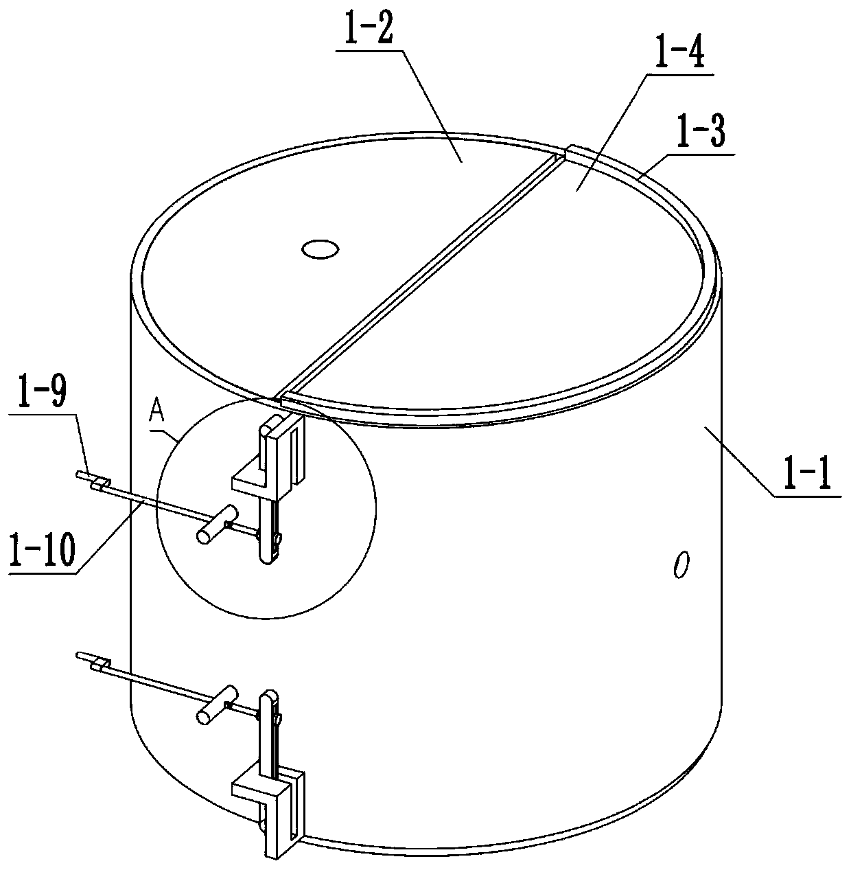
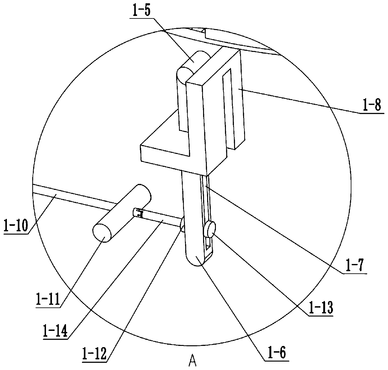
[0028] Combine below Figure 1-12 This embodiment, this embodiment will further explain Embodiment 1. The mixing chamber assembly 1 includes a stirring chamber 1-1, a stirring fixed cover 1-2, a sealing strip 1-3, a semicircular rotating cover 1-4, a rotating Cover shaft 1-5, rotating rod 1-6, rotating rod groove 1-7, rotating rod limit slide rail 1-8, rocker 1-9, threaded shaft 1-10, threaded rotating column 1-11, push block 1-12, pulling block 1-13 and hinge rod 1-14, the mixing chamber 1-1 is connected with two stirring fixed covers 1-2, and the two stirring fixed covers 1-2 are respectively connected with two semicircular rotary covers 1- 4-phase contact, the two semicircular rotary covers 1-4 are respectively connected with the two sealing strips 1-3, the two semicircular rotary covers 1-4 are respectively connected with the two rotary cover shafts 1-5, and the two rotary cover shafts 1-5 are rotationally connected with the mixing chamber 1-1, the two rotary cover shafts...

specific Embodiment approach 3

[0030] Combine below Figure 1-12This embodiment, this embodiment will further explain the first embodiment, the stirring assembly 2 includes the motor I 2-1, the motor I bracket 2-2, the pillar 2-3, the support plate 2-4, the motor I shaft 2- 5. Bevel gear Ⅰ2-6, bevel gear Ⅱ2-7, bevel gear Ⅲ2-8, bevel gear shaft Ⅰ2-9, bevel gear shaft Ⅱ2-10, bevel gear shaft Ⅲ2-11, bevel gear shaft Ⅳ2-12, spiral blade 2-13, sun gear 2-14, connecting rod 2-15, planetary gear fixed shaft 2-16, planetary gear 2-17, transmission housing Ⅰ 2-18, connecting sleeve 2-19 and transmission housing Ⅱ 2-20, motor Ⅰ 2-1 is connected with the motor Ⅰ support 2-2, the motor Ⅰ support 2-2 is connected with the pillar 2-3, the two pillars 2-3 are respectively connected with the two support plates 2-4, the motor Ⅰ 2-1 is connected with the The motor I shaft 2-5 is connected, the motor I shaft 2-5 is connected to the pillar 2-3 in rotation, the motor I shaft 2-5 is connected to two bevel gears I2-6, and the tw...


PUM


Abstract

The invention relates to the field of buildings, in particular to a building concrete mixing device. In constructional engineering, a concrete mixing device is necessary, and a traditional mixing device is low in mixing uniformity and inconvenient to discharge. The building concrete mixing device solves the problems, the building concrete mixing device is provided with two feeding openings and twodischarging openings; the functions of the feeding openings and the discharging openings can be switched to facilitate feeding and discharging; the rotating directions of two opposite spiral blades in a mixing chamber are opposite, so that concrete can be uniformly mixed; the mixing chamber rotates slowly when the spiral blades mix quickly, so that the mixing is more complete, and no missed mixing phenomenon exists; and the discharging openings are opened after completely mixing, and concrete is conveyed by a conveyor belt to complete discharging.

Description

technical field [0001] The invention relates to a construction field, in particular to a construction concrete mixing equipment. Background technique [0002] In construction engineering, concrete mixing and mixing equipment is indispensable. Traditional mixing equipment has low mixing uniformity and inconvenient unloading. The invention solves the above problems. Contents of the invention [0003] The purpose of the present invention is achieved through the following technical solutions: [0004] A construction concrete mixing equipment, comprising a mixing chamber assembly, a stirring assembly and a discharge assembly, characterized in that: the mixing chamber assembly is connected to the stirring assembly, and the stirring assembly is connected to the discharge assembly body connected. [0005] As a further optimization of the technical solution, the present invention is a kind of building concrete mixing equipment. The mixing chamber assembly includes a mixing chambe...

Claims


Application Information

Patent Timeline
IPC IPC(8): B28C5/16B28C7/16
CPCB28C5/16B28C7/16
Inventor 靳继民
Owner 靳继民
Why Eureka
Try Eureka