Evaporation source and vacuum evaporation system

A technology of evaporation source and evaporation material, which is applied in the directions of vacuum evaporation plating, sputtering plating, ion implantation plating, etc., which can solve the problems affecting the quality of the film layer and the evaporation material is easy to deteriorate.

Active Publication Date: 2020-02-11
BOE TECH GRP CO LTD +1
View PDF5 Cites 2 Cited by
  • Summary
  • Abstract
  • Description
  • Claims
  • Application Information

AI Technical Summary

Problems solved by technology

[0005] The embodiment of the present disclosure provides an evaporation source and a vacuum evaporation system, which can solve the problem that in the related art, after the heating wire increases the heating temperature, the evaporation material that is in a high temperature state for a long time is prone to deterioration, thereby affecting the formation of the substrate on the substrate. The quality of the film layer

Method used


Image

  • Evaporation source and vacuum evaporation system
  • Evaporation source and vacuum evaporation system
  • Evaporation source and vacuum evaporation system

Examples


Embodiment Construction

[0044] In order to make the purpose, technical solution and advantages of the present disclosure clearer, the implementation manners of the present disclosure will be further described in detail below in conjunction with the accompanying drawings.

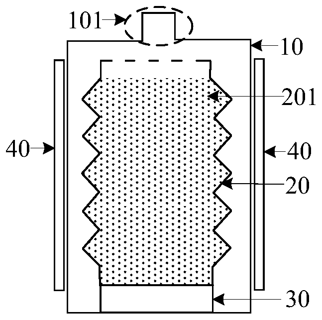
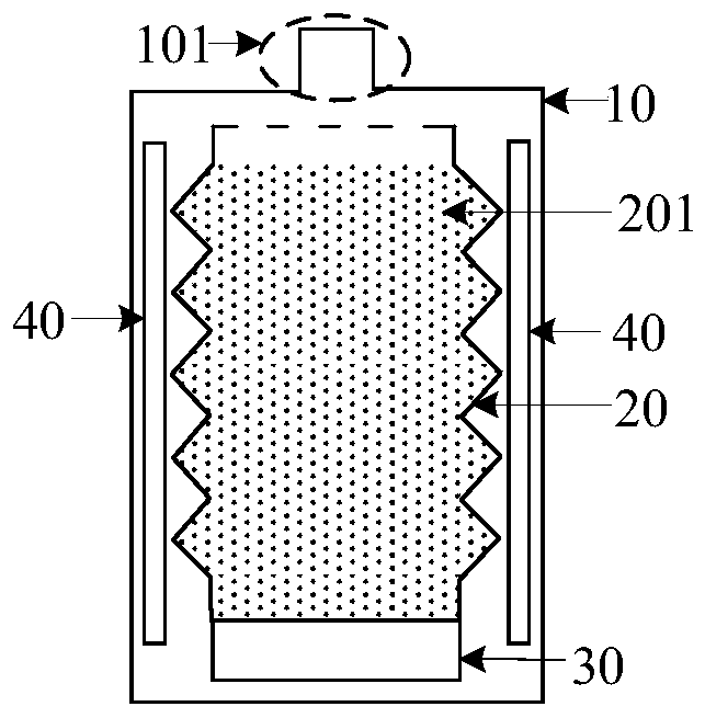
[0045] figure 1 It is a schematic cross-sectional view of an evaporation source provided by an embodiment of the present disclosure. Such as figure 1 As shown, the evaporation source may include a cavity 10 , a crucible 20 and a driving component 30 disposed in the cavity 10 , and a heating component 40 .

[0046] Wherein, the crucible 20 may be a retractable structure for placing the evaporation material 201 . One side of the cavity 10 (i.e. the top of the cavity 10) is provided with an air outlet 101, the driving assembly 30 is located on the side of the crucible 20 away from the air outlet 101, and the driving assembly 30 can be used to drive the crucible 20 toward the air outlet One side of the 101 shrinks. Optionally, the ...


PUM


Abstract

The invention discloses an evaporation source and a vacuum evaporation system and belongs to the technical field of display. The evaporation source comprises a cavity, a crucible and a driving assembly arranged in the cavity, and a heating assembly. The crucible is of a telescopic structure and is used for containing evaporation materials. An air outlet hole is formed in one side of the cavity, and the driving assembly is arranged on the side, away from the air outlet hole, of the crucible. The driving assembly is used for driving the side, close to the air outlet hole, of the crucible to contract. The heating assembly is used for heating the evaporation materials. According to the evaporation source and the vacuum evaporation system, due to the fact that the crucible is of a telescopic structure, the driving assembly can drive the side, close to the air outlet hole, of the crucible to contract. Thus, in the process that the evaporation materials in the crucible are reduced gradually,the distance between the evaporation materials and the air outlet hole can be maintained in a small range all the time, it can be ensured that the deposition rate of the evaporation materials is maintained stable without increasing the heating temperature, and therefore the phenomenon that the temperature is too high, and the quality of a film layer formed on a base plate is affected is avoided.

Description

technical field [0001] The present disclosure relates to the field of display technology, in particular to an evaporation source and a vacuum evaporation system. Background technique [0002] When performing vacuum evaporation on the substrate, usually the evaporation source, the mask and the substrate placed with the evaporation material are firstly placed in the vacuum chamber. Afterwards, the evaporation source can vaporize the evaporation material, and the vaporized evaporation material is deposited on the substrate through the hollow area of ​​the mask plate, and forms a film layer on the substrate. [0003] In the related art, the evaporation source may include a cavity, a crucible disposed in the cavity, and a heating wire. The crucible is used to place evaporation materials, and the top of the cavity and the crucible are provided with air outlets. The heating wire can heat the cavity to vaporize the evaporation material in the crucible, and the vaporized evaporatio...

Claims


Application Information

Patent Timeline
Patent Type & Authority Applications(China)
IPC IPC(8): C23C14/26C23C14/04C23C14/12
CPCC23C14/042C23C14/12C23C14/243C23C14/26
Inventor 邹清华黄俊淞
Owner BOE TECH GRP CO LTD
Why Eureka
Try Eureka