
Ducted positive crankcase ventilation plenum

A crankcase, ducted technology, applied in the direction of crankcase ventilation, fuel air intake, combustion air/combustion-air treatment, etc., can solve the problem of oil separator efficiency reduction, etc.

Pending Publication Date: 2020-02-11
FORD GLOBAL TECH LLC
View PDF1 Cites 0 Cited by
  • Summary
  • Abstract
  • Description
  • Claims
  • Application Information

AI Technical Summary

Problems solved by technology

Oil separator efficiency may be reduced due to turbulent flow field

Method used


Image

  • Ducted positive crankcase ventilation plenum
  • Ducted positive crankcase ventilation plenum
  • Ducted positive crankcase ventilation plenum

Examples


Embodiment Construction

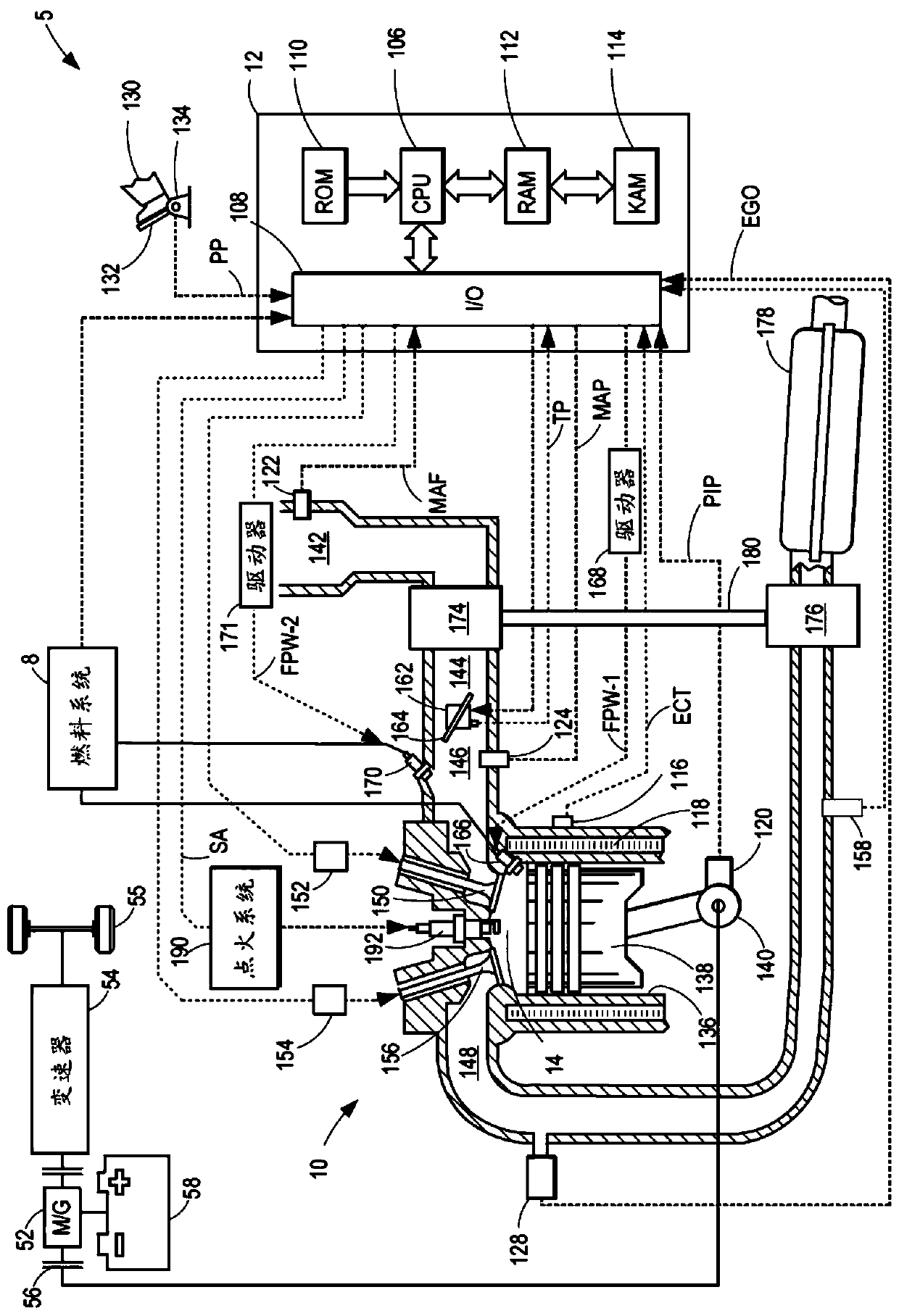
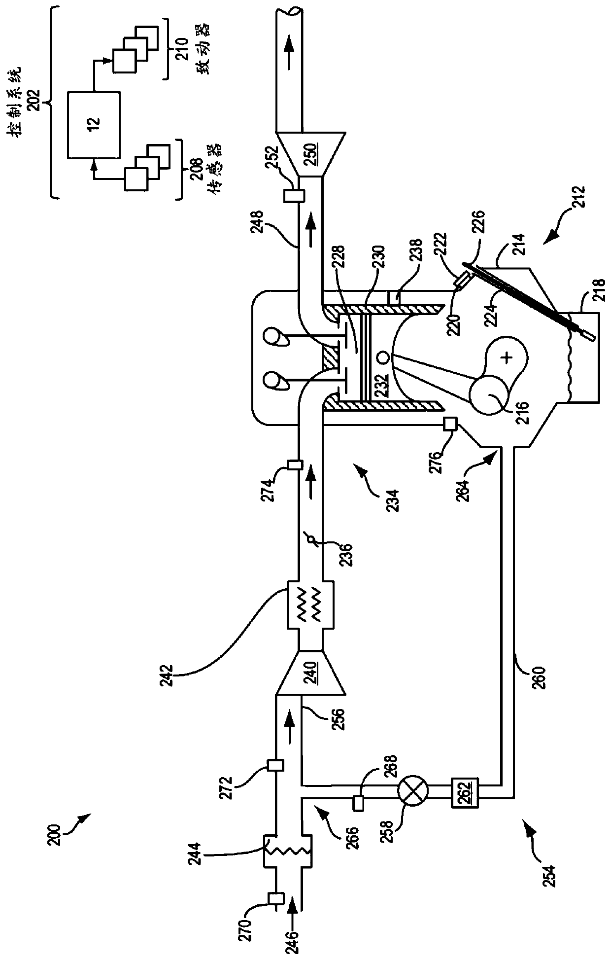
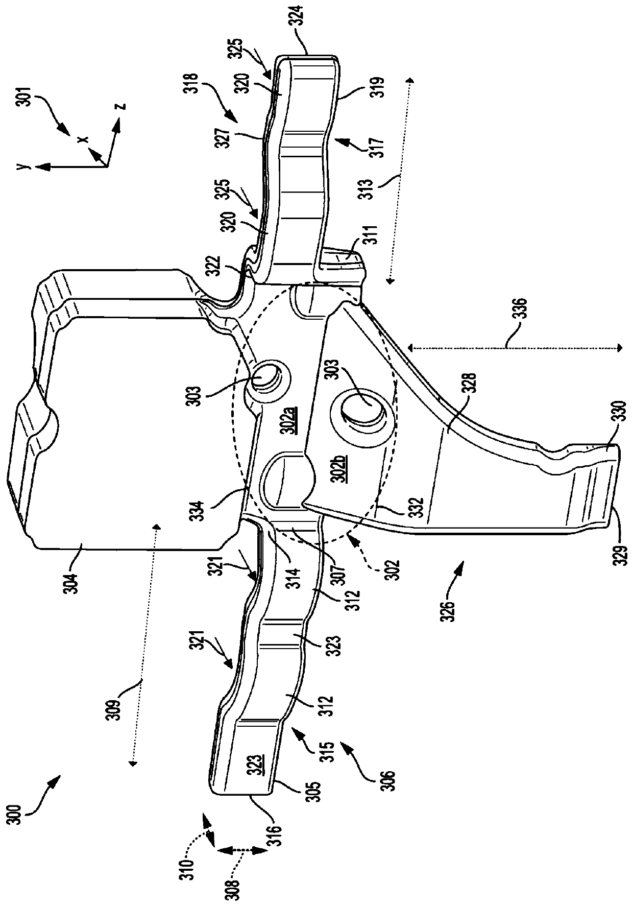
[0019] The following description relates to systems and methods for a PCV system. In an engine system, the crankcase can build up pressure due to blow-by of combustion gases. A PCV system may be installed in the engine, coupled to the exhaust system for recirculation of blow-by gases to the engine intake system. exist figure 1 A schematic diagram of an example of an engine system adapted with a PCV system is shown in . exist figure 2 An example of an engine is illustrated in , which depicts a single combustion chamber of the engine and the arrangement of the PCV system relative to the combustion chamber. The PCV system may include a ducted plenum having ducts coupled to a cylinder compartment of the engine. Blow-by gases from the cylinder compartment may be collected in a ducted plenum before passing through an oil separator arranged upstream of a PCV valve that controls the flow of gas from the crankcase to the engine intake system. exist image 3 An example of a ducte...


PUM


Abstract

A ducted positive crankcase ventilation plenum is provided. Methods and systems are provided for a ducted plenum of a positive crankcase ventilation system for an engine. In one example, the ducted plenum may include a plurality of ducts coupled to a central chamber and an oil separator and valve arranged downstream of the central chamber. The ducted plenum may vent gases from an engine crankcaseand deliver the vented gases to the engine intake system.

Description

technical field [0001] The description generally relates to systems for providing ventilation to an engine crankcase. Background technique [0002] During the power stroke of the piston of an engine cylinder, a portion of the gases combusted within the cylinder may leak through the ring that forms a seal around the base of the piston in a process known as blow-by. The escaping gases may accumulate in the crankcase, causing a build-up of pressure, which may cause deterioration of the oil stored in the crankcase to lubricate the movement of the pistons. To maintain oil integrity and relieve pressure in the crankcase, the engine may include a crankcase ventilation system to vent gases out of the crankcase and into the engine intake manifold. [0003] In some examples, a positive crankcase ventilation (PCV) system may use a steady state pressure differential to inject fresh air into the crankcase or to draw fresh air mixed with blowby gas out of the crankcase. The PCV system m...

Claims


Application Information

Patent Timeline
Patent Type & Authority Applications(China)
IPC IPC(8): F01M13/02F01M13/04F02M35/10
CPCF01M13/022F01M13/04F02M35/10222F01M13/0405F01M2013/0461F01M13/0416
Inventor 马修·邓恩保罗·休梅克达伦·西皮拉
Owner FORD GLOBAL TECH LLC
Learn More