Composite hydraulic oil pipe

A technology of hydraulic oil pipe and inner core pipe, applied in the field of hydraulic oil pipe, can solve the problems of high burst pressure, inability to adapt to use, poor functionality, etc., and achieve the effects of reducing the amount of expansion, strong practicability, and superior ozone resistance

Pending Publication Date: 2020-02-11
陆沈杰
View PDF0 Cites 0 Cited by
  • Summary
  • Abstract
  • Description
  • Claims
  • Application Information

AI Technical Summary

Problems solved by technology

[0004] Aiming at the deficiencies of the prior art, the present invention provides a composite hydraulic oil pipe, which solves the problem that the existing hydraulic oil pipes on the market are not suitable for non-mineral brake oil and mineral brake oil in the application process, and have certain Limitations, and most of the hydraulic tubing itself can only be used in a specific environment, and cannot adapt to the effect of being used in a variety of harsh environments. Its own functionality is poor, and it cannot withstand high blasting pressure.

Method used


Image

  • Composite hydraulic oil pipe
  • Composite hydraulic oil pipe

Examples


Embodiment Construction

[0018] The technical solutions in the embodiments of the present invention will be clearly and completely described below with reference to the accompanying drawings in the embodiments of the present invention. Obviously, the described embodiments are only a part of the embodiments of the present invention, but not all of the embodiments. Based on the embodiments of the present invention, all other embodiments obtained by those of ordinary skill in the art without creative efforts shall fall within the protection scope of the present invention.

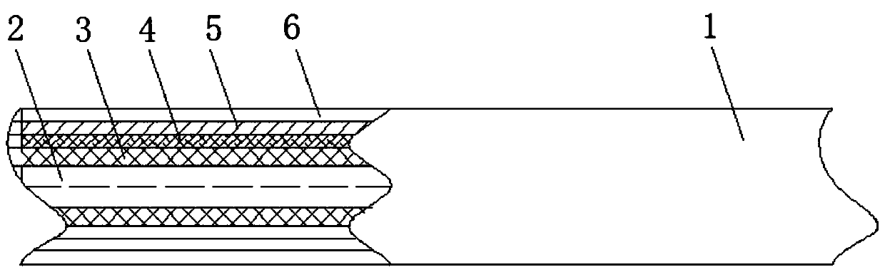
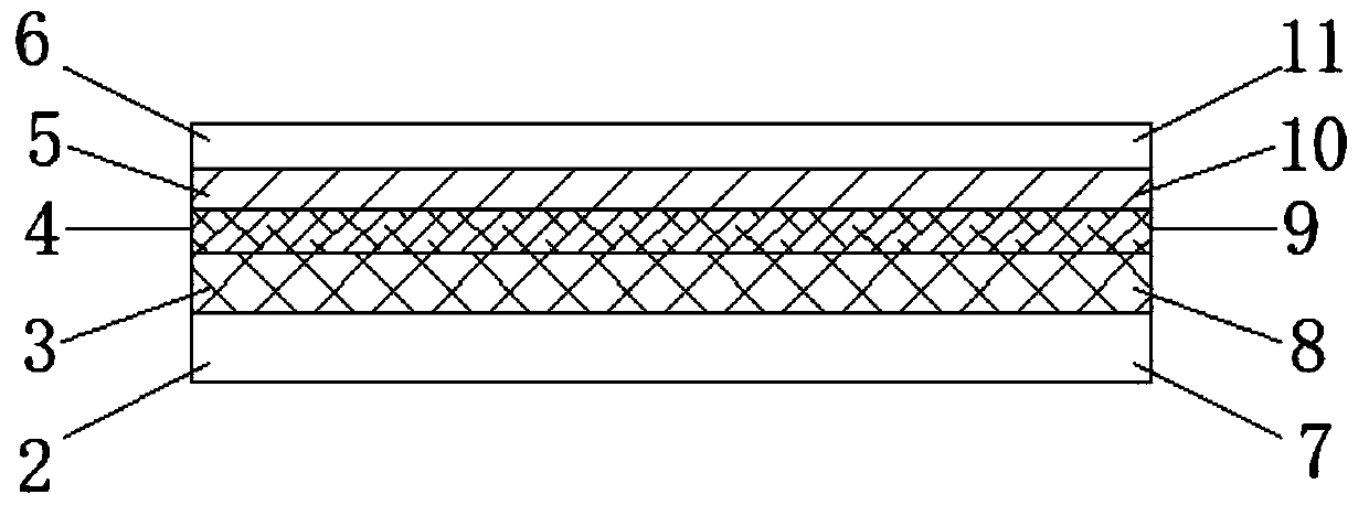
[0019] see Figure 1-2 , the embodiment of the present invention provides a technical solution: a composite hydraulic oil pipe, including an oil pipe main body 1, a high molecular polymer inner core pipe 2, a vinyl dipped vinyl braided layer 3 and a nylon braided double layer 4, the oil pipe main body 1 The inner part includes a high molecular polymer inner core tube 2, a vinyl dipped vinyl braided layer 3, a nylon braided double laye...


PUM


Abstract

The invention discloses a composite hydraulic oil pipe. The composite hydraulic oil pipe comprises an oil pipe main body, a high-molecular polymer inner core pipe, a dipped vinylon braided layer and anylon braided double layer; and the oil pipe main body internally comprises the high-molecular polymer inner core pipe, the dipped vinylon braided layer, the nylon braided double layer, a stainless steel wire braided layer and a polyamine outer layer pipe. According to the composite hydraulic oil pipe, by braiding the dipped vinylon braided layer on the outside of the high-molecular polymer innercore pipe, the dipped vinylon braided layer is attached to the inner core pipe more closely, then, the nylon braided double layer is braided on the dipped vinylon braided layer, and finally, the stainless steel wire braided layer is pressed on the outside of the nylon braided double layer; and accordingly, through the layer-by-layer progressive braiding mode, the problem that the braided layer isnot compactly braided on the inner core pipe can be effectively solved, the swelling amount of the oil pipe is decreased, the bursting strength of the hydraulic oil pipe can be greatly improved, thewhole structure is compact, and the practicality is high.

Description

technical field [0001] The invention relates to the technical field of hydraulic oil pipes, in particular to a composite hydraulic oil pipe. Background technique [0002] The hydraulic oil pipes on the market are not suitable for non-mineral brake fluids and mineral brake fluids in the process of application. They have certain limitations in use, and most of the hydraulic oil pipes themselves can only be used in specific environments. The effect of being used in a variety of harsh environments has poor functionality and cannot withstand high burst pressure. SUMMARY OF THE INVENTION [0003] (1) Technical problems solved [0004] Aiming at the deficiencies of the prior art, the present invention provides a composite hydraulic oil pipe, which solves the problem that the existing hydraulic oil pipes on the market are not suitable for non-mineral brake oil and mineral brake oil during the application process, and have certain characteristics during use. Limitations, and most...

Claims


Application Information

Patent Timeline
Patent Type & Authority Applications(China)
IPC IPC(8): F16L11/10F16L57/02F16L57/06
CPCF16L11/10F16L57/02F16L57/06
Inventor 陆沈杰
Owner 陆沈杰
Why Eureka
Try Eureka