
Automatic locking and relocking system of ultra-stable laser device and working method thereof

An automatic locking and laser technology, applied in lasers, laser parts, phonon exciters, etc., can solve the problems of limited application scope of ultra-stable lasers, complicated locking process of ultra-stable lasers, and limited commercialization of ultra-stable lasers. Achieve the effect of reducing the time required, increasing the probability of successful locking, and reducing time

Inactive Publication Date: 2020-02-11
NAT TIME SERVICE CENT CHINESE ACAD OF SCI
View PDF4 Cites 7 Cited by
  • Summary
  • Abstract
  • Description
  • Claims
  • Application Information

AI Technical Summary

Problems solved by technology

[0003] Most of the ultra-stable lasers are in the laboratory state, which requires the manual operation of professionals to realize the locking of the ultra-stable lasers, thus limiting the commercialization of ultra-stable lasers and their application in the future space field
First of all, the locking process of the ultra-stable laser is relatively complicated. Generally, several switches and buttons need to be fine-tuned in the locking process, which is not easy for ordinary users to operate, which limits the application range of the ultra-stable laser; secondly, the ultra-stable laser’s It takes a long time to manually lock the process. Under normal circumstances, it takes 1-2 minutes to lock

Method used


Image

  • Automatic locking and relocking system of ultra-stable laser device and working method thereof
  • Automatic locking and relocking system of ultra-stable laser device and working method thereof

Examples


Embodiment Construction

[0035] The present invention will be further described below in conjunction with the accompanying drawings.

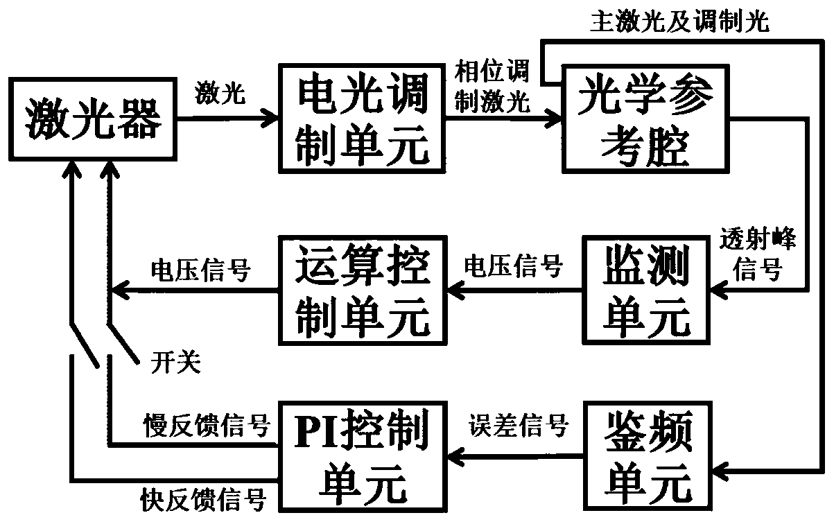
[0036] Such as figure 1 Shown, the present invention comprises the following steps:

[0037] 1) The light output by the laser is phase-modulated by the electro-optic modulation unit, and the modulated light becomes three kinds of light with different frequency components, that is, the main light and two beams of modulated light, in which the frequency of the main light is the same as that of the light before modulation, and the two beams The modulation frequency of the modulated light is just opposite;

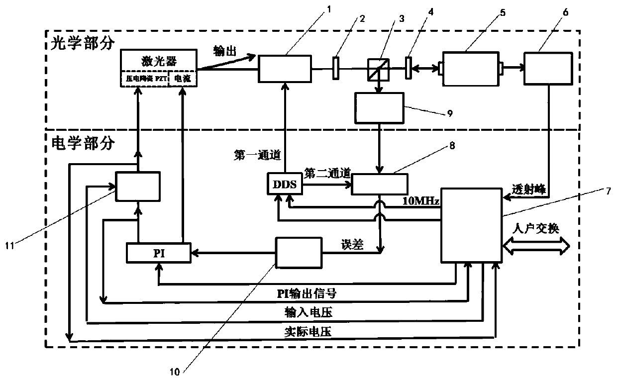
[0038]2) After the main light and modulated light reach the surface of the optical reference cavity 5 , most of the light is reflected by the cavity mirror at the front end of the optical reference cavity 5 , and only a small amount of light enters the interior of the optical reference cavity 5 .

[0039] 3) The main light after resonating with the optical reference ...


PUM


Abstract

The invention discloses an automatic locking and relocking system of an ultra-stable laser device and a working method thereof. The system comprises an electro-optical modulator, a first wave plate, apolarization splitting prism, a second wave plate, an optical reference cavity, a monitoring unit, a photoelectric detector, an operation control unit, a frequency discrimination unit, a proportionalintegral control circuit (PI) and a voltage driver, wherein resonance is generated through the output frequency of the laser device and the optical reference cavity, parameters of the proportional-integral control circuit (PI) are adjusted through the operation control unit, so automatic locking of the ultra-stable laser device is realized, moreover, the monitoring unit is used for monitoring a locking state of the ultra-stable laser, so the unlocked laser device can be locked again. The system is advantaged in that the probability of successful locking of the laser device is improved, the time required by the locking process of the laser device is shortened, the locking quality of the laser device is guaranteed, and the commercialization and space application process of the ultra-stablelaser device is accelerated.

Description

technical field [0001] The invention belongs to the technical field of high-precision time and frequency, and relates to an automatic locking and relocking system of an ultra-stable laser and a working method thereof. Background technique [0002] High-precision time-frequency signals are directly related to national security and social development, and are widely used in national defense construction, scientific research, and national infrastructure construction. With technological breakthroughs such as laser precision spectroscopy and optical frequency combs, the frequency stability and accuracy of cold atomic optical clocks have entered 10 -18 The order of magnitude is about two orders of magnitude higher than the existing cesium atomic fountain clock, which will greatly improve the accuracy of the current time-frequency system. The ultra-stable laser with ultra-high frequency stability is used as the local oscillator of the cold atomic optical clock, directly It determi...

Claims


Application Information

Patent Timeline
IPC IPC(8): H01S3/094H01S3/13
CPCH01S3/094026H01S3/1305
Inventor 焦东东张林波刘涛董瑞芳张首刚
Owner NAT TIME SERVICE CENT CHINESE ACAD OF SCI
Learn More