
Novel anchoring nail

An anchor nail, a new type of technology, applied in the direction of fixers, internal bone synthesis, fastening devices, etc., can solve the problems of easy friction of soft tissue, blunt top, increased difficulty of self-tapping, etc., to increase self-tapping pressure and reduce discomfort , the effect of reducing difficulty

Pending Publication Date: 2020-02-14
SHANGHAI NINTH PEOPLES HOSPITAL SHANGHAI JIAO TONG UNIV SCHOOL OF MEDICINE
View PDF1 Cites 1 Cited by
  • Summary
  • Abstract
  • Description
  • Claims
  • Application Information

AI Technical Summary

Problems solved by technology

The medical anchor can fix the anchor wire in the groove between the nut and the thread, so that it is not easy to cut the anchor wire during the operation and ensure the smooth progress of the operation. However, in the above case, there is no overflow groove, which makes the top relatively blunt. Self-tapping is inconvenient to use, and there is no passage for bone debris to be squeezed into the bone to increase the risk of infection, and further increase the difficulty of self-tapping, and the existing design is that the screwdriver fixes the anchor nail through the inner buckle and then self-tapping implants condyle, but the design of the fixation area is relatively wide and thick. After the anchor screw is implanted, a large part of the bone surface is exposed, which is easy to rub against the soft tissue and cause postoperative discomfort for the patient.

Method used


Image

  • Novel anchoring nail
  • Novel anchoring nail
  • Novel anchoring nail

Examples


Embodiment Construction

[0019] The following will clearly and completely describe the technical solutions in the embodiments of the present invention with reference to the accompanying drawings in the embodiments of the present invention. Obviously, the described embodiments are only some, not all, embodiments of the present invention. Based on the embodiments of the present invention, all other embodiments obtained by persons of ordinary skill in the art without making creative efforts belong to the protection scope of the present invention.

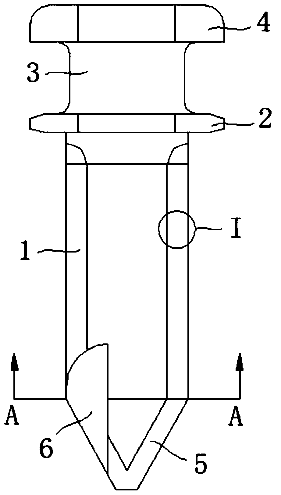
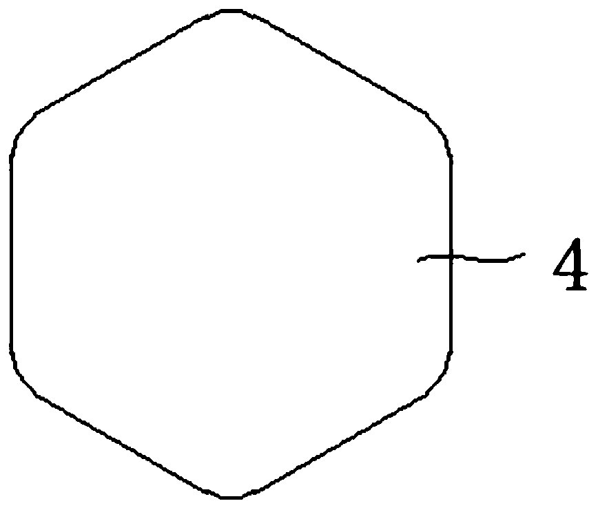
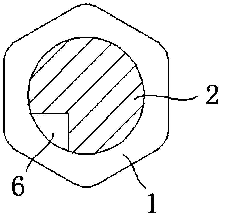
[0020] see Figure 1-4 , a new type of anchor nail, including a nail body 1, a stopper 2, a connecting column 3, a top buckle 4, a self-tapping tip 5 and a threaded edge 6, the surface of the nail body 1 is provided with a thread 101, and the gap between the threads 101 The gap is 0.8mm, and the height is 0.35mm. There is a 0.1mm fillet between the bottom of the left side of the thread 101 (that is, the back force side) and the nail body 1, and the bottom of t...


PUM


Abstract

The invention discloses a novel anchoring nail. The novel anchoring nail comprises a nail body, a stopper, a connecting column, a top button, a self-tapping tip end and a threaded cutting edge, wherein the stopper is arranged on the upper part of the nail body; and the upper part of the nail body is fixedly connected with the top button through the connecting column. According to the novel anchoring nail disclosed by the invention, through mutual cooperation among the nail body, threads, the stopper, the connecting column, the top button, the self-tapping tip end and the threaded cutting edge,the novel anchoring nail is realized. The design of an overflow groove is added in a threaded area, so that the tip end of a screw is sharper, and the self-tapping pressure intensity is increased, and thus, the anchoring nail passes through a cortical bone more easily in a drilling way; meanwhile, due to the overflow groove, bone chips can be discharged from the overflow groove, so that incrementof infection risk caused by accumulating the bone chips in bones is avoided, and the difficulty of drilling the anchoring nail into the bones is also reduced; and because of the design of thinner screwdriver buckle area, the exposure size of the anchoring nail outside the bones is reduced while the anchoring nail is stably clamped and self-tapping is carried out at the same time, and a discomfortsense of a patient caused by rubbing of muscles is reduced.

Description

technical field [0001] The invention relates to the technical field of medical anchoring nails, in particular to a novel anchoring nail. Background technique [0002] A medical anchor refers to an anchor used in medicine, such as application number: CN200820156083.3, which discloses a medical anchor comprising a nut and a screw rod, the nut is connected to the screw rod, and the screw rod is provided with threads. A groove is formed on the nut along its outer circumference toward its center, the groove is arc-shaped, and the arc protrudes toward the center of the nut. The medical anchor can fix the anchor wire in the groove between the nut and the thread, so that it is not easy to cut the anchor wire during the operation and ensure the smooth progress of the operation. However, in the above case, there is no overflow groove, which makes the top relatively blunt. Self-tapping is inconvenient to use, and there is no passage for bone debris to be squeezed into the bone to incr...

Claims


Application Information

Patent Timeline
Patent Type & Authority Applications(China)
IPC IPC(8): A61B17/86
CPCA61B17/86A61B17/8625
Inventor 杨驰陈敏洁张善勇白果郑吉驷
Owner SHANGHAI NINTH PEOPLES HOSPITAL SHANGHAI JIAO TONG UNIV SCHOOL OF MEDICINE
Learn More