
Drillable casing floating hoop floating shoe device

A technology of floating shoes and hoops, which is applied in the direction of wellbore/well valve devices, earthwork drilling, wellbore/well components, etc. It can solve the influence of valve core sealing performance and forward and reverse pressure bearing capacity, PDC bit two Difficulties in drilling in the first spud and restrictions on drilling progress, etc., to achieve the effects of reducing cementing accidents, shortening drilling cycle, and reducing drilling costs

Active Publication Date: 2017-01-04
CHANGQING GUJING OF CNPC CHUANQING DRILLING ENG
View PDF6 Cites 0 Cited by
  • Summary
  • Abstract
  • Description
  • Claims
  • Application Information

AI Technical Summary

Problems solved by technology

[0002] The existing floating hoop and floating shoes for well cementing have a non-integral structure of the valve core. When applied to a horizontal well with a large inclination angle, the sealing performance of the valve core and the forward and reverse pressure bearing capacity will be seriously affected, and even cause the cement slurry to flow back, resulting in Well cementing accident, in addition, the inner casing of the valve core is made of steel structure material, the second spud drilling of the PDC bit is difficult, and the construction time is long, which seriously restricts the drilling progress

Method used


Image

  • Drillable casing floating hoop floating shoe device
  • Drillable casing floating hoop floating shoe device
  • Drillable casing floating hoop floating shoe device

Examples


Embodiment 1

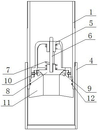
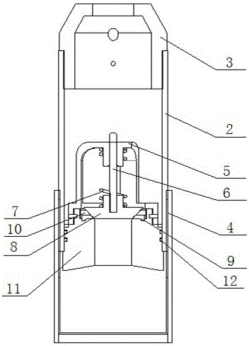
[0021] The structure diagram of the floating hoop in the drillable casing floating hoop shoe is as follows: figure 1 As shown, the schematic diagram of the floating shoe structure is shown in figure 2 As shown, it at least includes a floating hoop shell 1 and a floating shoe shell 2, and the upper edge of the floating hoop shell has connecting threads, wherein the upper end of the floating shoe shell 2 is connected with a drainage cover 3 through its connecting thread, and the floating hoop The lower edge of the floating shoe shell has threads on both sides inside and outside, the lower edge of the floating hoop floating shoe shell is connected to the collar 4 through its external thread, and the lower edge of the floating hoop floating shoe shell is connected to the valve seat 11 through its internal thread, and the valve seat The upper part of 11 is threadedly connected with spring seat 5, and the axial center position of spring seat 5 and valve seat 11 has a through hole. ...

Embodiment 2

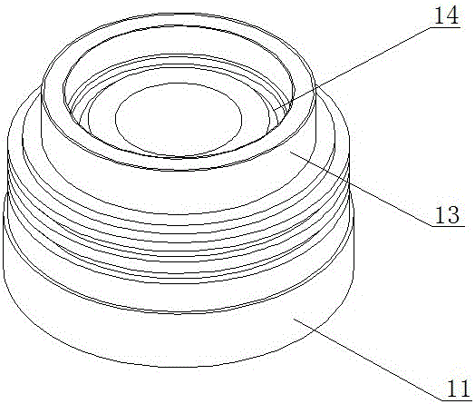
[0024] A sealing ring 12 is also sleeved between the valve seat 11 and the floating hoop floating shoe housing to seal the connection. The structure of the valve seat 11 is as follows: image 3 As shown, the outside of the middle part of the valve seat 11 is an external thread connected with the lower edge of the floating hoop floating shoe housing and an annular groove for placing the sealing ring 12. The upper part of the valve seat 11 has an annular convex edge 13, and the inner side of the annular convex edge is an annular The pressure cap fixing groove 14, the pressure cap 9 is crimped in the pressure cap fixing groove 14, and a gasket 10 is also fixed between the upper surface of the pressure cap 9 and the inner side wall of the annular convex edge.

[0025] The structure of pressure cap 9 is as Figure 4 As shown, the pressure cap 9 is an annular structure, and the annular inner wall of the pressure cap 9 is a slope with a closed end. Fixing hole for valve stem 6, see ...

Embodiment 3

[0028] The structure of spring seat 5 is as Figure 6 As shown, it is composed of a base 15, an upper spring seat 16, and a fixed rod 17; wherein the base 15 is an annular structure, and the inner wall of the base 15 is an internal thread, and the base 15 protrudes along the outer wall of the valve seat 11 through its internal thread. The upper end of the base 15 is fixedly connected with the upper spring seat 16 through the fixed rod 17, wherein there are three fixed rods 17, the upper spring seat 16 is coaxial with the ring-shaped base 15, and the axial center position of the upper spring seat 16 is provided with a socket The through hole of the valve rod 6, the upper spring seat 16 bottom is a spring holder, and the spring 7 upper end is fixedly connected with the spring holder.

[0029] The cement slurry enters the top through the gap between the spring seat 5 three fixed rods after the valve seat 11 is pushed away.


PUM


Abstract

The invention relates to a drillable casing pipe float collar float shoe device which at least comprises a float collar shell and a float shoe shell. Connection threads are arranged on the top rim of the float collar shell and the top rim of the float shoe shell. The upper end of the float shoe shell is connected with a drainage cover through the connection threads. Threads are arranged on the inner sides and the outer sides of the lower rims of the float collar shell and the float shoe shell. The lower rims of the float collar shell and the float shoe shell are connected with couplings through outer threads. The drillable casing pipe float collar float shoe device is characterized in that the lower rims of the float collar shell and the float shoe shell are connected with valve seats through inner threads; spring seats are connected above the valve seats through threads. Through holes are formed in axial centers of the spring seats and the valve seats. The upper portions of valve rods are connected into the through holes at the axial centers of the spring seats in an insertion mode. The lower portions of the valve rods are fixed with valve elements which are arranged at the through holes of the axial centers of the valves seats in a blocking mode. The valve rods are sleeved with springs in a connected mode. The upper ends of the springs are fixedly connected with the spring seats. The lower ends of the springs are fixedly connected with the valve elements. The drillable casing pipe float collar float shoe device can prevent cement paste from flowing backwards and reduce well cementation accidents. Triple drilling is prepared for, the construction time is saved, the drilling cost is reduced and the drilling period is shortened.

Description

technical field [0001] The invention relates to the field of cementing tools, in particular to a drillable casing floating hoop floating shoe device used in oil development cementing operations. Background technique [0002] The existing floating hoop and floating shoes for well cementing have a non-integral structure of the valve core. When applied to a horizontal well with a large inclination angle, the sealing performance of the valve core and the forward and reverse pressure bearing capacity will be seriously affected, and even cause the cement slurry to flow back, resulting in Well cementing accident, in addition, the inner casing of the valve core is made of steel structure material, the second spud drilling of the PDC bit is difficult, and the construction time is long, which seriously restricts the drilling progress. Contents of the invention [0003] The object of the present invention is to provide a drillable casing floating hoop floating shoe device which can e...

Claims


Application Information

Patent Timeline
Patent Type & Authority Patents(China)
IPC IPC(8): E21B33/13E21B34/06
Inventor 王大权窦虎清雷东瑞李德伟张立伟李峰
Owner CHANGQING GUJING OF CNPC CHUANQING DRILLING ENG
Learn More