Form plate system of prefabricated U-shaped beam

A U-shaped, formwork technology, applied in the direction of manufacturing tools, ceramic forming machines, ceramic forming cores, etc., can solve the problems of difficulty in formwork adjustment, long installation and removal time, low work efficiency, etc., and achieve high construction efficiency and beautiful appearance , cost-saving effect

Active Publication Date: 2020-02-14
北京城建中南土木工程集团有限公司
View PDF8 Cites 0 Cited by
  • Summary
  • Abstract
  • Description
  • Claims
  • Application Information

AI Technical Summary

Problems solved by technology

[0004] The above-mentioned existing technical solutions have the following defects: Since the side forms need to be installed and disassembled block by block each time they are hoisted, the installation and removal time is long and the work efficiency is low; It is very easy to cause collision and deformation, which brings difficulties to the adjustment of the template in the later stage

Method used


Image

  • Form plate system of prefabricated U-shaped beam
  • Form plate system of prefabricated U-shaped beam
  • Form plate system of prefabricated U-shaped beam

Examples


Embodiment Construction

[0039] The present invention will be further described in detail below with reference to the accompanying drawings.

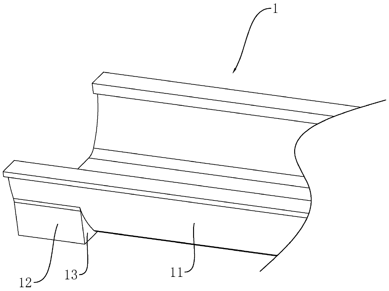
[0040] refer to figure 1 , because the lower structure of the middle section and the end section of the U-shaped beam 1 is different, the U-shaped beam 1 is divided into a middle section 11 and an end section 12, and a vertical transition surface is formed at the connection between the end section 12 and the middle section 11 13.

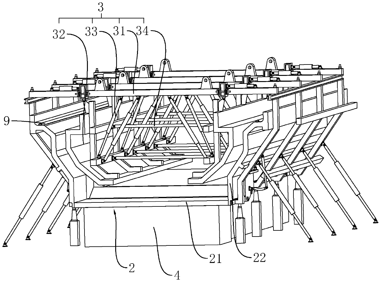
[0041] refer to figure 2 , the formwork system of the prefabricated U-shaped beam, including the outer mold unit 2, the inner mold unit 3 erected directly above the outer mold unit 2 and the end molds respectively arranged at both ends of the outer mold unit 2, the outer mold unit 2, the inner mold unit 3 and the end mold A cavity for casting the U-shaped beam 1 is formed between the molds.

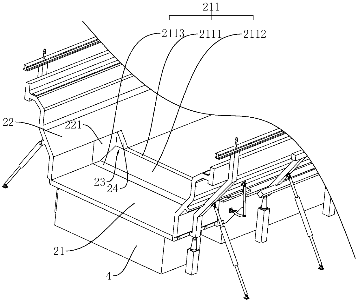
[0042] The outer mold unit 2 includes a bottom mold 21 and a side mold 22 . The bottom mold 21 is arranged on the base 4 , and the base 4 e...


PUM


Abstract

The invention relates to a form plate system of a prefabricated U-shaped beam and relates to the technical field of prefabricated beam form plates. The form plate system of the prefabricated U-shapedbeam comprises an outer from unit, an inner form unit erected over the outer form unit, and end forms arranged at the two ends of the outer form unit respectively. The outer form unit comprises a bottom form arranged on a pedestal and side forms arranged on the two sides of the bottom form respectively, and a movable bottom plate for opening and closing the bottom from is arranged at the part, where the middle section and the end sections of the U-shaped beam are connected, of the bottom form. One end of the movable bottom plate is hinged to the bottom form, the other end of the movable bottomplate is connected with the bottom from through bolts, movable side plates for opening and closing the side forms are arranged at the parts, located at the movable bottom plate, of the side forms, the upper ends of the movable side plates are hinged to the side forms, and the lower ends of the movable side plates are connected with movable side plates through bolts. The form plate system of the prefabricated U-shaped beam has the advantages of being convenient to operate, needless for removing the side forms and high in construction efficiency.

Description

technical field [0001] The invention relates to the technical field of prefabricated beam formwork, in particular to a formwork system for prefabricated U-shaped beams. Background technique [0002] U-shaped beam is a U-shaped concrete prefabricated beam with open thin walls. Compared with ordinary box girder, U-shaped beam has the advantages of low beam height, good noise reduction effect, high section space utilization, safe driving, beautiful appearance and good visual effect. At present, many intercity light rails and subways in China use prefabricated U-shaped beams as the upper structure. The U-shaped beams include a middle section and end sections respectively set at both ends of the middle section. The bottom of the end section is convex downward. out the bottom of the middle section. [0003] At present, the prefabrication of the U-shaped beam requires the use of formwork. The existing formwork includes an outer mold unit, an inner mold unit suspended above the out...

Claims


Application Information

Patent Timeline
Patent Type & Authority Applications(China)
IPC IPC(8): B28B7/00B28B7/30
CPCB28B7/00B28B7/0002B28B7/0014B28B7/30
Inventor 任振江娄志会吴海炎于海亮李玲孙士鼎黄锡阳范欣荣高毅波刘智磊
Owner 北京城建中南土木工程集团有限公司
Why Eureka
Try Eureka