
Double-pulse combustion device with common-chamber time-sharing ignition output

A dual-pulse and combustor technology, which is applied to rocket engine devices, machines/engines, jet propulsion devices, etc., can solve problems such as inability to dynamically compensate for temperature loss, difficulty in meeting battery life, and low proportion of charge mass. Achieve the effect of reducing the space of structural parts, improving space utilization, and avoiding insufficient inflation or overpressure

Active Publication Date: 2020-02-14
湖北三江航天红林探控有限公司
View PDF3 Cites 6 Cited by
  • Summary
  • Abstract
  • Description
  • Claims
  • Application Information

AI Technical Summary

Problems solved by technology

[0002] The current mature gas generators are mostly used to inflate the storage tank of the attitude control power system, pressurize the propellant storage tank or drive the turbine. Its technical characteristics are one-time charge, one-time start-up, fixed gas output, and inflation often occurs during the pressure building process. Insufficient or overpressure, it is impossible to dynamically compensate for temperature loss, and it is accompanied by large high-frequency impact vibration; in addition, single-chamber free-loading charges are mostly used, and the proportion of charge mass is low, which requires a large space and weight to meet the same gas production. Therefore, it is difficult to meet the applications with long battery life, low overload, controllable output and limited space

Method used


Image

  • Double-pulse combustion device with common-chamber time-sharing ignition output
  • Double-pulse combustion device with common-chamber time-sharing ignition output
  • Double-pulse combustion device with common-chamber time-sharing ignition output

Examples


Embodiment Construction

[0029] In order to make the purpose, technical solutions and advantages of the embodiments of the present invention clearer, the technical solutions in the embodiments of the present invention will be clearly and completely described below in conjunction with the drawings in the embodiments of the present invention. Obviously, the described embodiments It is a part of embodiments of the present invention, but not all embodiments. Based on the embodiments of the present invention, all other embodiments obtained by persons of ordinary skill in the art without making creative efforts belong to the protection scope of the present invention.

[0030]Below in conjunction with accompanying drawing, the present invention is described in further detail:

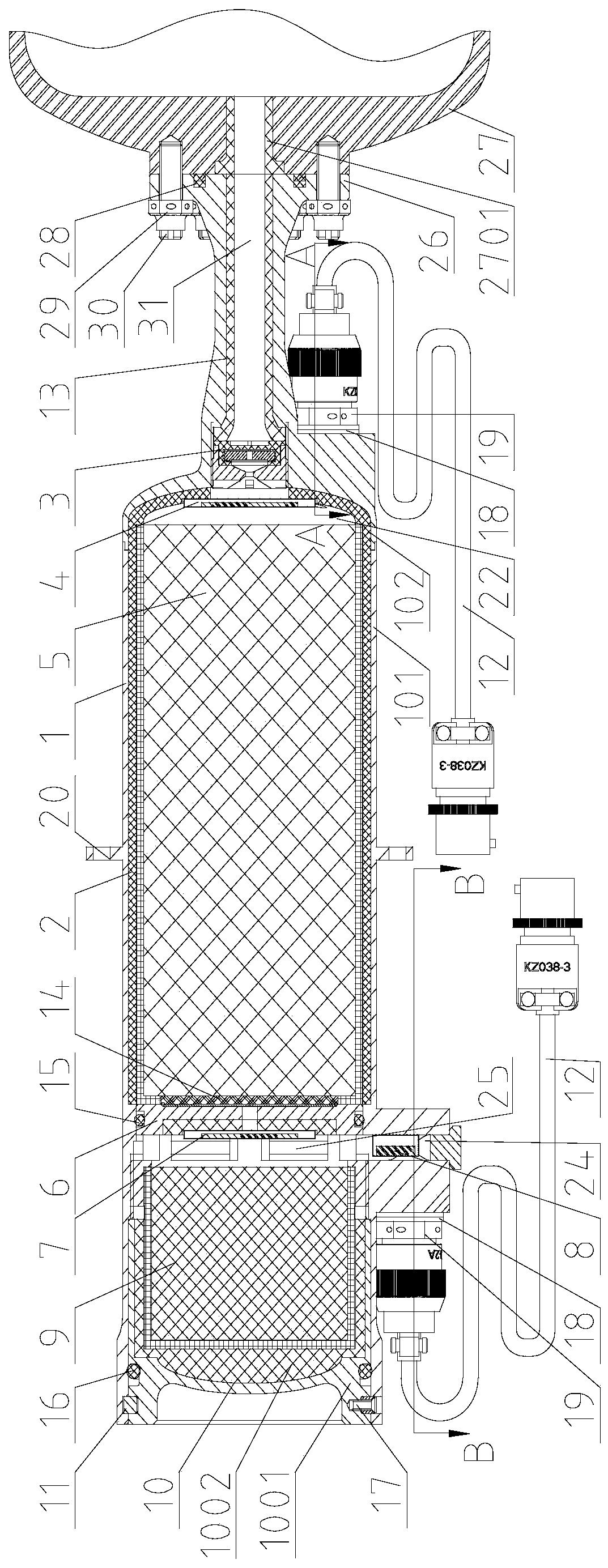
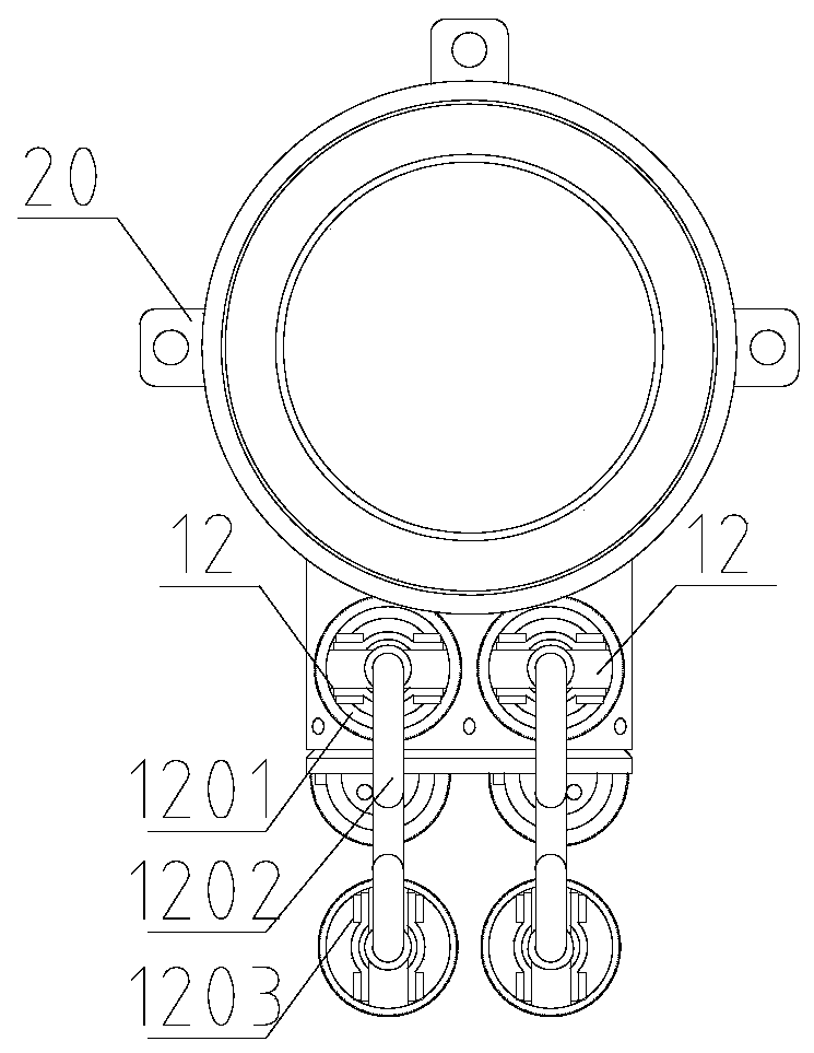
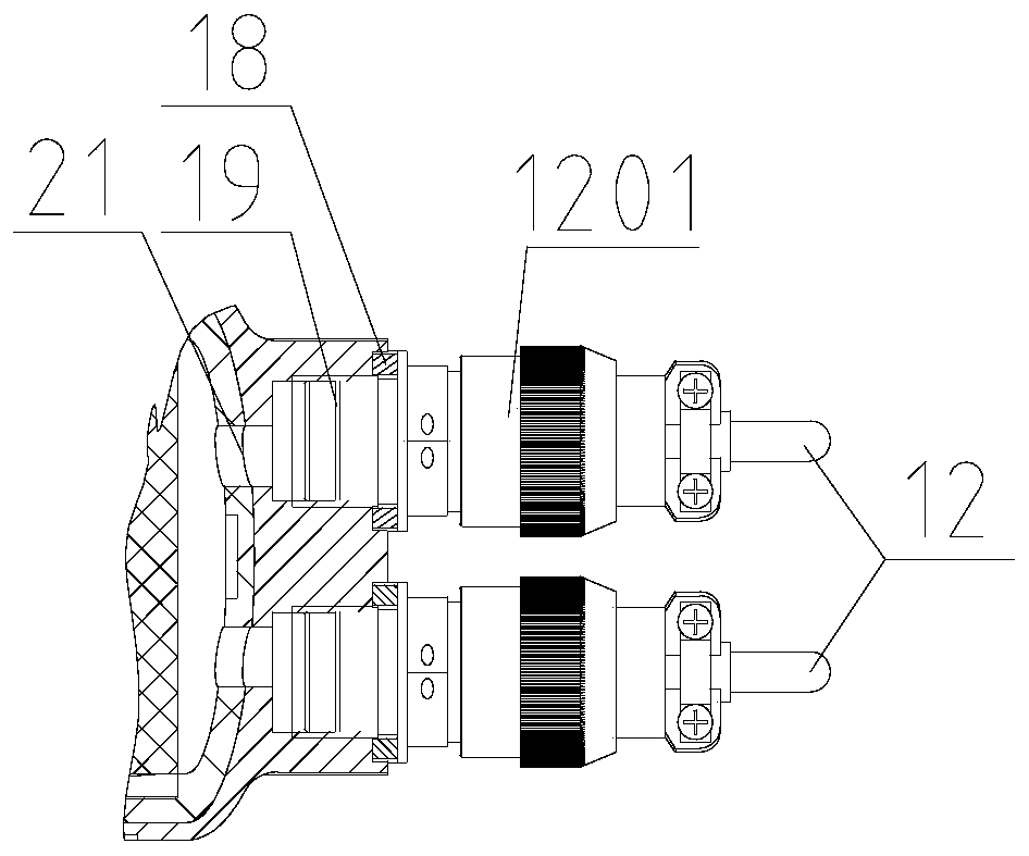
[0031] Such as Figure 1 to Figure 4 As shown, according to the present invention, a double-pulse burner with time-sharing ignition output in a common chamber includes: a housing part 1, a primary charge 5, a secondary charge 9, a pr...


PUM


Abstract

The invention discloses a double-pulse combustion device with a common-chamber time-sharing ignition output. The first-stage charging and the second-stage charging are installed in a shell component in series, a first-stage ignition component is installed on the shell component and is connected with the first-stage charging in a matching mode, a second-stage ignition component is installed on theshell component and is connected with the second-stage charging in a matching mode, the first-stage charging and the second-stage charging are separated into two independent combustion units by adopting a partition layer component, a one-way valve component is arranged between the first-stage charging and an exhaust port of the shell component, and the sealing end of the shell component adopts a snap ring component to fix end cover components to the shell body component, and the sealing is achieved. According to the technical scheme, the space utilization rate is improved, so that the charge quantity is increased, dynamic compensation of the gas quantity of a gas storage device is realized, insufficient inflation or overpressure is effectively avoided, the reliability of ignition gas production is improved, and the double-pulse combustion device has the advantages that the structure is compact and reasonable, the installation is simple, and the extended application is flexible.

Description

technical field [0001] The invention relates to the technical field of gas generators, in particular to a dual-pulse gas generator with time-sharing ignition output in a common room. Background technique [0002] The current mature gas generators are mostly used to inflate the storage tank of the attitude control power system, pressurize the propellant storage tank or drive the turbine. Its technical characteristics are one-time charge, one-time start-up, fixed gas output, and inflation often occurs during the pressure building process. Insufficient or overpressure, it is impossible to dynamically compensate for temperature loss, and it is accompanied by large high-frequency impact vibration; in addition, single-chamber free-loading charges are mostly used, and the proportion of charge mass is low, which requires a large space and weight to meet the same gas production. Therefore, it is difficult to meet the applications with long battery life, low overload, controllable out...

Claims


Application Information

Patent Timeline
Patent Type & Authority Applications(China)
IPC IPC(8): F02K9/08F02K9/32F02K9/95
CPCF02K9/08F02K9/32F02K9/95
Inventor 虞国军郝雪杰常江
Owner 湖北三江航天红林探控有限公司
Learn More