Cutter set for crushing pump

A technology for cutting knives and crushing pumps, applied to pumps, pump components, non-variable pumps, etc., can solve problems such as low cutting efficiency, increased vibration or shaft power, and frequent failures, so as to reduce on-site maintenance costs and improve The effect of using abrasion resistance and reducing the chance of entanglement

Pending Publication Date: 2020-02-14
江苏芬奇工业设备制造有限公司
View PDF0 Cites 0 Cited by
  • Summary
  • Abstract
  • Description
  • Claims
  • Application Information

AI Technical Summary

Problems solved by technology

[0003] Because the conveying medium contains acetic acid and polyester, it is very easy to form small particles and fibers entangled and blocked in the crushing pump and pipeline.
The existing structure of the crushing pump is that the outer circle of the cutting wheel is used in conjunction with the sheath, and the cut medium enters the pump impeller through the grid plate, the cutting efficiency is low, and the long-term operation of the pump is often caused by the accumulation of particles and fibers in the medium during the operation of the pump. The cutting wheel, the sheath and the grid will be aggravated or locked, vibration will occur or the shaft power will increase or even stop, which will affect the working efficiency and service life. The cutting wheel, the sheath and the grid are also the most frequent faults during operation.
[0004] The existing design of the sheath is to add several sets of spacers in the annular space, and use the relative displacement of the cutting wheel and the spacers for cutting. Often, the spacers follow the cutting objects in the sheath and the cutting wheel. The cutting efficiency is low, and the separation The blade is easily damaged; and the cutting wheel and the sheath spacer are easily entangled and locked, which is also the part with the most failures during operation

Method used


Image

  • Cutter set for crushing pump
  • Cutter set for crushing pump
  • Cutter set for crushing pump

Examples


Embodiment Construction

[0016] The present invention will be described in further detail below in conjunction with the accompanying drawings.

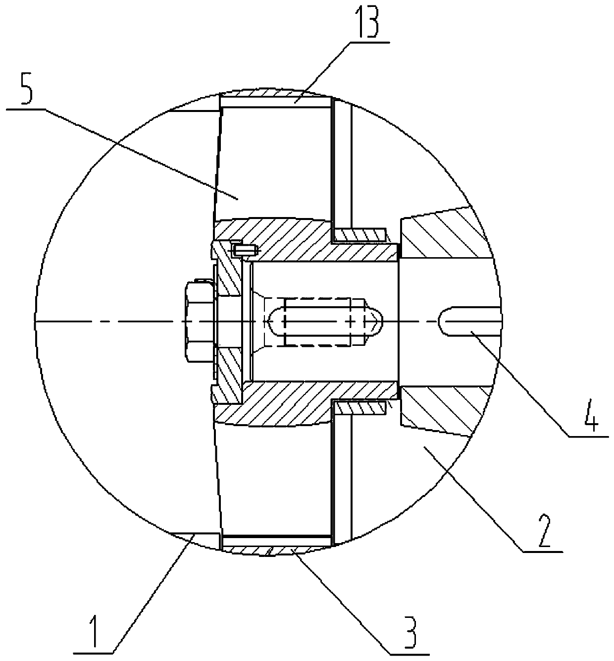
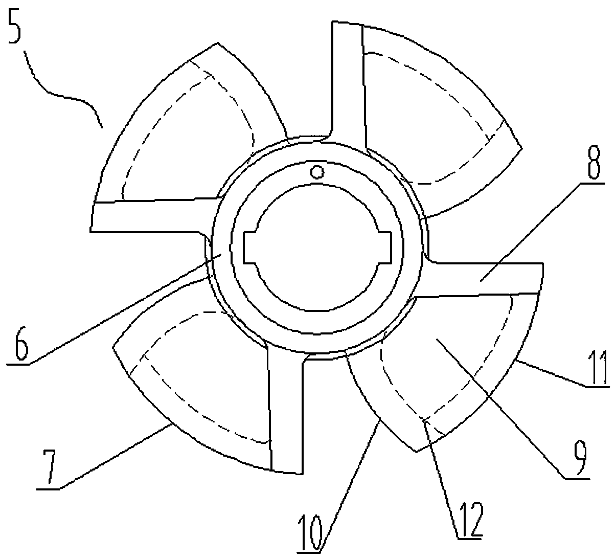
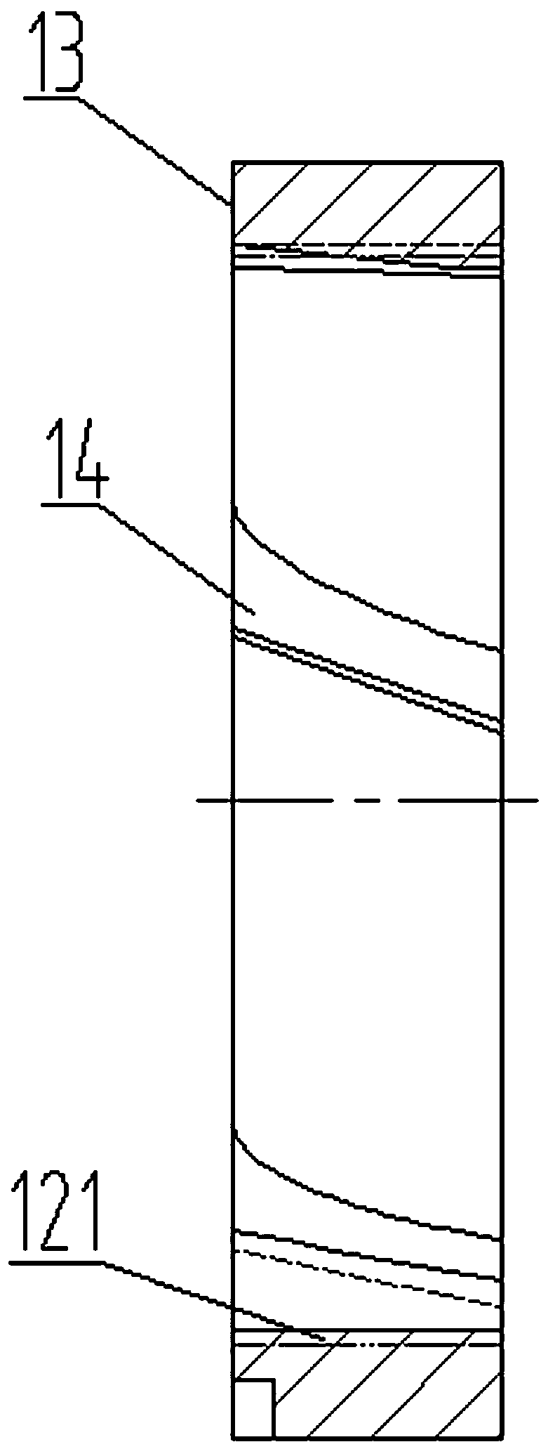
[0017] Figure 1-3 As shown, a cutting knife set for a crushing pump includes a cutting wheel 5 sleeved and fixed on the front end of the impeller 2 on the pump shaft 4, and a cutting sleeve 13 that is sleeved outside the cutting wheel and embedded in the pump body 2 with a clearance fit. The cutting wheel 5 includes a rim 6 and blades 7. The rim 6 is connected to the pump shaft 4 via a key and is fixed and locked. A plurality of blades 7 are uniformly connected to the outer periphery of the rim 6. The blades 7 include ribs 8 and blades. 9. The rib part 8 is a rib structure extending outward in a straight line or arc from the rim, and one side of the leaf part 9 is connected to the upper side of the rib part 8, and the leaf part 9 goes from one side to the other side around the circumferential direction The height of the side plane is reduced and extended (o...


PUM


Abstract

The invention relates to a cutter set for a crushing pump. The set comprises a cutting wheel and a cutting sleeve, wherein the cutting wheel is fixed to the front end of an impeller on a pump shaft ina sleeve manner, the cutting wheel is connected to the exterior of the cutting wheel in a clearance fit sleeve mode, and is embedded in a pump body or a pump cover or a suction pipe, the cutting wheel comprises a rim and blades, the plurality of blades are uniformly distributed on the periphery of the rim, the blades comprise rib parts and blade parts, the rib parts are fillet structures extending outward in a linear or arc mode from the rim, one side edges of the blade parts are connected to the side edges of the upper parts of the rib parts, the blade parts extend from one side edges to theother side edges in the circumferential direction with the plane height reduced, the other side edges of the blade parts are provided with cutting edges and a plurality of oblique grooves which are not parallel to the axis of the cutting sleeve are uniformly distributed on the inner hole wall of the cutting sleeve. According to the cutter set, the cutting efficiency of the cutting wheel and the cutting efficiency of the cutting sleeve can be effectively improved, winding and locking are prevented, and the service life is prolonged.

Description

technical field [0001] The invention belongs to the technical field of industrial water pumps, and mainly relates to a cutting knife set for crushing pumps. Background technique [0002] PTA is one of the important bulk organic raw materials, widely used in various aspects of the national economy such as chemical fiber, light industry, electronics, construction, etc. The application of PTA is relatively concentrated. More than 90% of the world's PTA is used to produce polyethylene terephthalate, and the rest is used as polytrimethylene terephthalate (PTT) and polybutylene terephthalate. (PBT) and other raw materials for products. my country's polyester output ranks first in the world, and it is a veritable polyester powerhouse. In the polyester industry, the demand for crushing pumps for conveying slurry and chopping slurry is increasing, and it is required that the pump must run stably, have a low failure rate, and be easy and quick to maintain. [0003] Because the conv...

Claims


Application Information

Patent Timeline
Patent Type & Authority Applications(China)
IPC IPC(8): F04D7/04F04D29/00F04D29/02F04D29/70B02C18/18
CPCF04D7/045F04D29/708F04D29/026F04D29/007B02C18/18
Inventor 肖爱华
Owner 江苏芬奇工业设备制造有限公司
Why Eureka
Try Eureka