
Fiber grating-based soil matric suction quasi-distributed in-situ measurement method and apparatus

A technology of matrix suction and fiber grating, applied in the direction of measuring device, phase influence characteristic measurement, soil material test, etc., to achieve the effect of convenient operation, improved spatial resolution, and small soil disturbance

Active Publication Date: 2020-02-14
NANJING UNIV +1
View PDF6 Cites 4 Cited by
  • Summary
  • Abstract
  • Description
  • Claims
  • Application Information

AI Technical Summary

Problems solved by technology

There are no relevant research reports on the use of this technology to determine the matric suction in unsaturated soils at home and abroad.

Method used


Image

  • Fiber grating-based soil matric suction quasi-distributed in-situ measurement method and apparatus
  • Fiber grating-based soil matric suction quasi-distributed in-situ measurement method and apparatus
  • Fiber grating-based soil matric suction quasi-distributed in-situ measurement method and apparatus

Examples


Embodiment 1

[0079] Indoor calibration experiment using the method and device of the present invention for a matrix suction sensor. Specific steps are as follows:

[0080] Step 1. Weigh the sensor rod to obtain the quality of the clay rod;

[0081] Step 2. For the same clay stick, configure different water states of the clay stick by controlling the water content, and combine the filter paper suction test method to calibrate 16 to 20 groups of matrix suction of the clay stick at different saturations, and fit the matrix suction of the clay stick The relationship with the change of water saturation is the soil-water characteristic curve of the clay stick;

[0082] Step 3. Fully mix and stabilize the manufactured and packaged matrix suction sensor with water. The matrix suction sensor is a matrix suction sensor based on fiber Bragg grating pulse heating, and is composed of a clay rod, an optical fiber, a heating resistance wire, and an optical fiber grating;

[0083] Step 4: During the dry...

Embodiment 2

[0088] The method and device of the invention are used to carry out in-situ tests for distributed measurement of soil matrix suction, and to monitor the soil ice content of different depths of soil. The soil of a clayey soil area in Nanjing was selected as the test site.


PUM

PropertyMeasurementUnit
thermal conductivityaaaaaaaaaa

Abstract

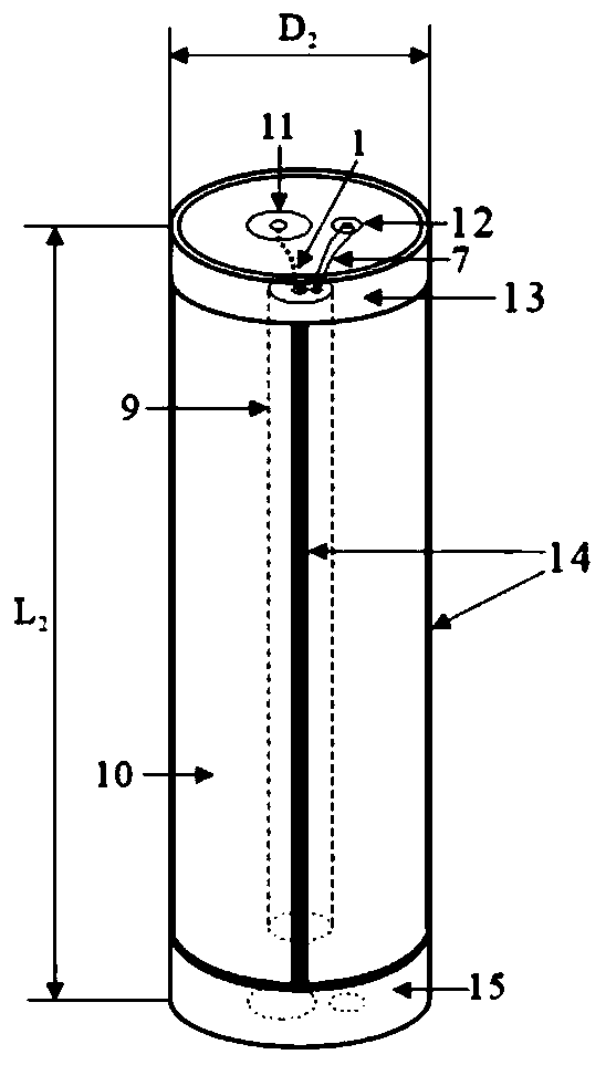
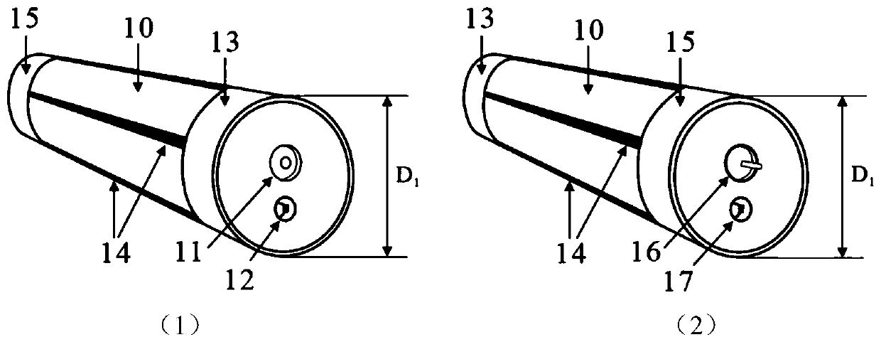
The invention discloses a fiber grating pulse heating-based soil matric suction quasi-distributed in-situ measurement method and apparatus, including a heating direct current power supply, a high temperature-sensitive insulation tube (in which a resistance wire and a fiber grating are built), a clay bar, and a fiber grating demodulator, and a computer for analyzing and processing monitoring data.A matric suction sensor that is manufactured and pre-saturated is buried in measured soil, and then left to stand for 24 hours to achieve a water potential balance between the clay bar and the soil. The heating power supply is connected to perform pulse heating on the resistance wire built in the matric suction sensor, and heat is diffused, through the high heat-sensitive insulation tube with goodheat conduction performance, into the clay bar wrapped by the high heat-sensitive insulation tube. The fiber grating built in the high heat-sensitive insulation tube is sensitive to a temperature change, and a temperature change value can be obtained by converting fiber grating wavelength data collected by the fiber grating demodulator. Finally, a function relationship between matric suction of the clay bar and the temperature change value is established through a calibration test, and then soil matric suction corresponding to the temperature change value is obtained according to the water potential balance. In the measurement method, the temperature change value is obtained through the thermal pulse heating, and the soil matric suction under a sensor water potential balance condition isobtained according to a calibration relationship between the matric suction and the temperature change value. The invention can realize fast, continuous, remote, high-precision, quasi-distributed soilmatric suction measurement.

Description

technical field [0001] The invention discloses a distributed in-situ measurement method and device for soil matrix suction with fiber Bragg gratings (optical fiber gratings), and relates to the technical field of soil matrix suction measurement. Background technique [0002] In unsaturated soil, the soil is composed of soil particles, water and air, that is, in addition to the pore water pressure in the soil, there is also pore air pressure. At the interface between pore water and pore air, water has surface tension. Suction in soil includes matrix suction and osmotic suction (solute suction). Due to the existence of meniscus, the pore water pressure and pore air pressure are not equal. When the pore water pressure (u_w) is less than the pore air pressure (u_a), The difference between the two (u_a-u_w) is called the matrix suction. For the vast majority of unsaturated soils, the suction exists. When it encounters sudden rainfall or flooding, it is easy to cause rapid satur...

Claims


Application Information

Patent Timeline
Patent Type & Authority Applications(China)
IPC IPC(8): G01N21/41G01N33/24G01K11/32G01K11/3206
CPCG01N21/412G01N33/24G01K11/3206
Inventor 王家琛朱鸿鹄韦超倪钰菲裴华富程刚张春新王东辉郭子奇
Owner NANJING UNIV
Learn More