Plunger pump rotating speed measuring method and device

A technology of speed measurement and plunger pump, which is applied in the field of hydraulic system and can solve the problem of difficulty in installing speed sensor

Inactive Publication Date: 2020-03-17
COMAC +1
View PDF3 Cites 1 Cited by
  • Summary
  • Abstract
  • Description
  • Claims
  • Application Information

AI Technical Summary

Problems solved by technology

[0006] The purpose of the present invention is to provide a method for measuring the rotational speed of a plunger pump to solve the problem of difficulty in installing a rotational speed sensor near the plunger pump

Method used


Image

  • Plunger pump rotating speed measuring method and device
  • Plunger pump rotating speed measuring method and device
  • Plunger pump rotating speed measuring method and device

Examples


Embodiment Construction

[0026] The present invention will be further described below in conjunction with specific embodiments and accompanying drawings, but the protection scope of the present invention should not be limited thereby.

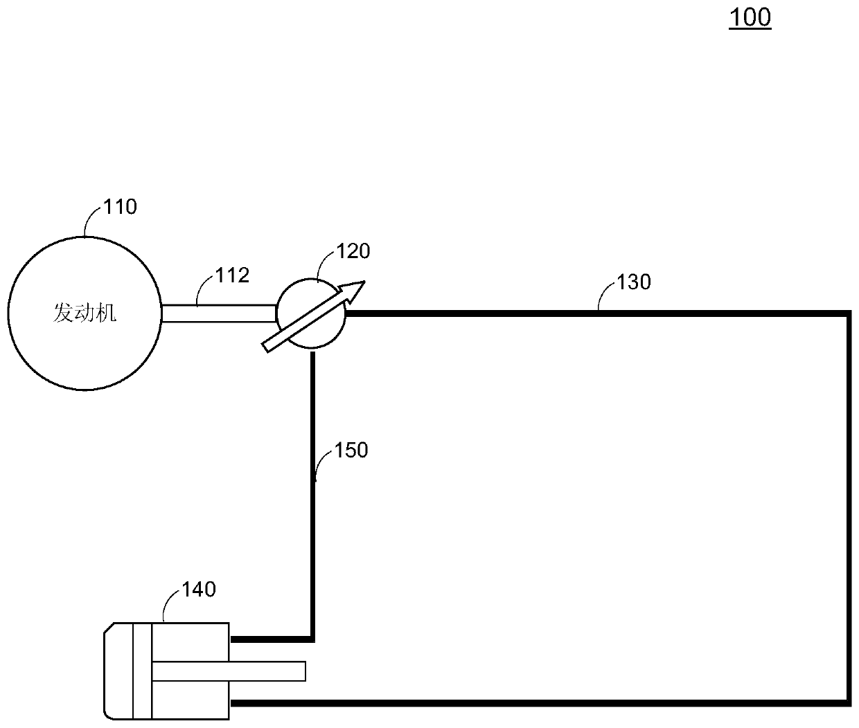
[0027] figure 1 is a system architecture diagram of a hydraulic system 100 according to an embodiment of the present invention. figure 1 It is shown that the hydraulic system 100 includes an engine 110, a drive shaft 112 connected to the engine 110, a plunger pump 120 connected to the drive shaft 112, and the plunger pump 120 is connected to the actuator 140 through a hydraulic line 130 and a return line 150 . The engine 110 may also be a power source such as an electric motor, an auxiliary power, a ram air turbine, or the like. When the hydraulic system 100 is working, the engine 110 rotates and drives the plunger pump 120 to rotate through the drive shaft 112 . The plunger pump 120 may include one or more plungers, and each plunger rotates with the plunger pump 12...


PUM


Abstract

The invention discloses a plunger pump rotating speed measuring method and device. The device can comprise a strain gauge sensor, wherein the strain gauge sensor is located on a hydraulic pipeline connected with the output end of a plunger pump; a data acquisition module which is used for acquiring a measurement signals on the strain gauge sensor when the plunger pump outputs pulsating fluid to ahydraulic pipeline; and a signal processing module which is used for determining the pulsation frequency of the pulsating fluid in the hydraulic pipeline on the basis of the energy spectral density ofthe measurement signals and determining the rotating speed of the plunger pump on the basis of the pulsation frequency.

Description

technical field [0001] The present invention generally relates to a hydraulic system, in particular to a method and device for measuring the rotational speed of a plunger pump. Background technique [0002] The hydraulic system is powered by a motor, uses a hydraulic pump to convert mechanical energy into liquid pressure, and then drives the load to perform linear reciprocating or rotary motion. A hydraulic system that uses a plunger pump as the key power element. The hydraulic plunger pump works under high speed and high pressure conditions. It converts the mechanical energy of power machinery (such as engine transmission case, electric motor, auxiliary power, ram air turbine, etc.) into hydraulic energy (pressure, flow) output , thus providing hydraulic power to the user system. [0003] The aircraft hydraulic system is used to provide hydraulic power to user systems such as the flight control system, landing gear system, and thrust reverser system. The aircraft hydraul...

Claims


Application Information

Patent Timeline
Patent Type & Authority Applications(China)
IPC IPC(8): G01P3/26
CPCG01P3/263
Inventor 史杰
Owner COMAC
Why Eureka
Try Eureka